ER Diagrams: The Key to Understanding Database Design
ER diagram (Entity-Relationship diagram) is a tool used for database design. It shows the structure and relationship of data in a graphical way. For beginners, understanding ER diagram is the first step to master database design. Today, ProcessOn editor will show you the basic concepts, components and applications of ER diagram.
ER diagram is a graphical representation method for describing entities and their relationships. It was proposed by Chinese-American computer scientist Chen Pinshan in 1976 to help design and build database models. ER diagram intuitively shows the structure of the database through three basic elements: entity, attribute and relationship. Let's first take a look at what the ER diagram looks like.
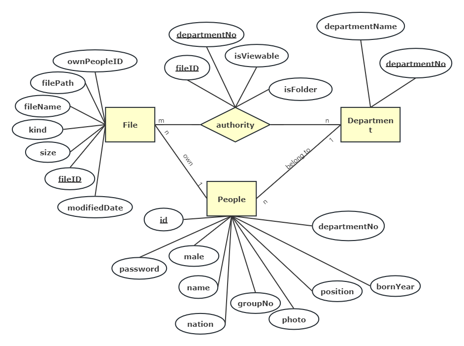
ER diagram of file management system
In the ER diagram above, the relationship between people, files, departments and their authority management in the file management system is expressed. We can see that there are rectangles, ovals, diamonds, lines and some text on the lines in the ER diagram. What do they mean? The following editor will introduce them to you one by one .
1. Entity
Entity is the basic building block in ER diagram, which represents a distinguishable object in the real world. Rectangles are usually used in drawings to represent entities; entities can be concrete (such as students, teachers, books) or abstract (such as courses, departments). Each entity usually has a unique Primary Key that uniquely identifies each entity instance.
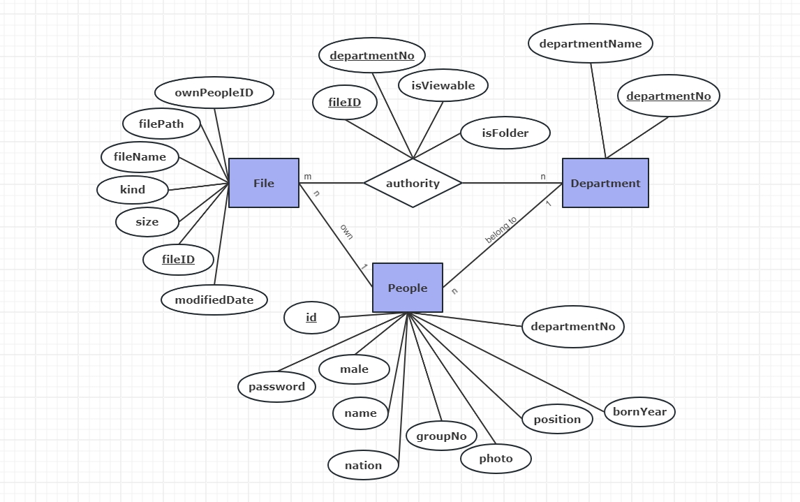
Identify the entity
2. Attribute
Attributes are characteristics or properties of an entity, usually represented by ellipses in drawings. Each entity can have multiple attributes that describe its characteristics. For example, a student entity may have attributes such as name, student number, and gender. Attributes can be simple attributes (indivisible) or composite attributes (dividable into multiple sub-attributes).
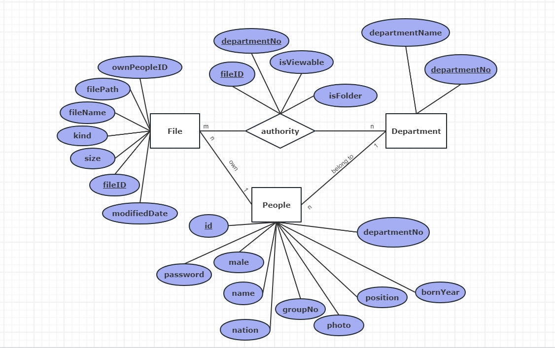
Determine the properties
3. Relationship
Relationships describe the association between entities and are usually represented by diamonds in diagrams. Relationships can be one-to-one (1:1), one-to-many (1:n), or many-to-many (m:n). For example, the relationship between students and courses is a many-to-many relationship because a student can take many courses and a course can have many students. Attributes are connected to entities by lines, and relationships are connected to related entities by lines.
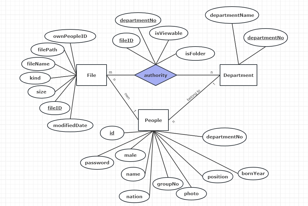
Determine the relationship
Intuitive display of data structure: ER diagrams display the structure and relationships of data in a graphical way, making it easier to understand and communicate.
Assisted database design: In the process of database design, ER diagram is an important tool that helps designers build a reasonable data model and ensure the integrity and consistency of data.
Documented data model: ER diagram can be used as a document of database design, recording the structure of the data model and providing a reference for subsequent database maintenance and expansion.
Identify entities: First, determine the entities that need to be included in the database. This step requires analyzing the actual business and finding the key objects.
Determine attributes: Determine attributes for each entity to describe the characteristics of the entity. Be careful to distinguish between simple attributes and compound attributes to ensure the integrity of the attributes.
Define relationships: Identify the relationships between entities and describe the associations between them. Specify the type of relationship (one-to-one, one-to-many, or many-to-many) and add the necessary attributes to the relationship.
Draw ER diagram: As the saying goes, if you want to do your work well, you must first sharpen your tools. So today the editor recommends a sharp tool, that is ProcessOn. ProcessOn is a free online professional drawing tool with many built-in graphics drawing functions, including ER diagrams. The most important thing is that you don’t need to download any client to use ProcessOn, you can use it online .
Using ProcessOn not only makes it easier for you to draw ER diagrams, but also allows you to see numerous ER diagram works in the template community. It also supports sharing and collaboration, allowing you to share your drawn ER diagrams so that your classmates can intuitively see the data structure you designed, record database design documents, and view them at any time.

ProcessOn professional online ER diagram drawing tool
Create an entity: Open ProcessOn, click New Flowchart, select ER Diagram in More Diagrams, drag the entity rectangle under the ER diagram into the canvas, and enter the entity name in the rectangle .
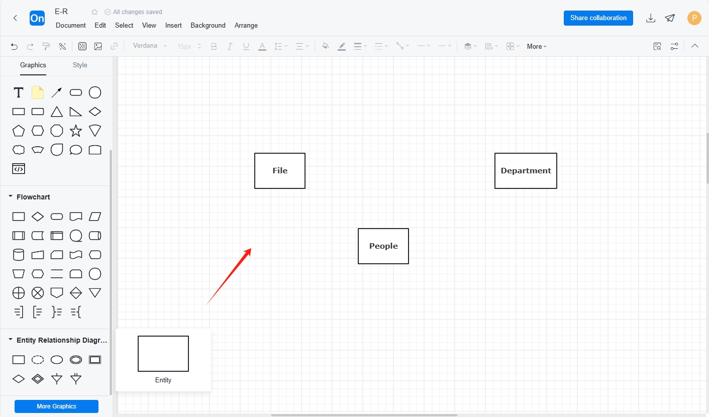
Creating entities in ProcessOn
Create attributes: Drag the attribute oval from the bottom of the ER diagram on the left and place it on the canvas. Enter the attribute name in the oval and connect the entity with the corresponding attribute with a line .

Creating properties in ProcessOn
Create a relationship: Drag the relationship diamond from the bottom of the ER image on the left and place it on the canvas. When connecting the diamond box representing the relationship to the entity with a line, write 1, n, or m next to the line to indicate the type of relationship.
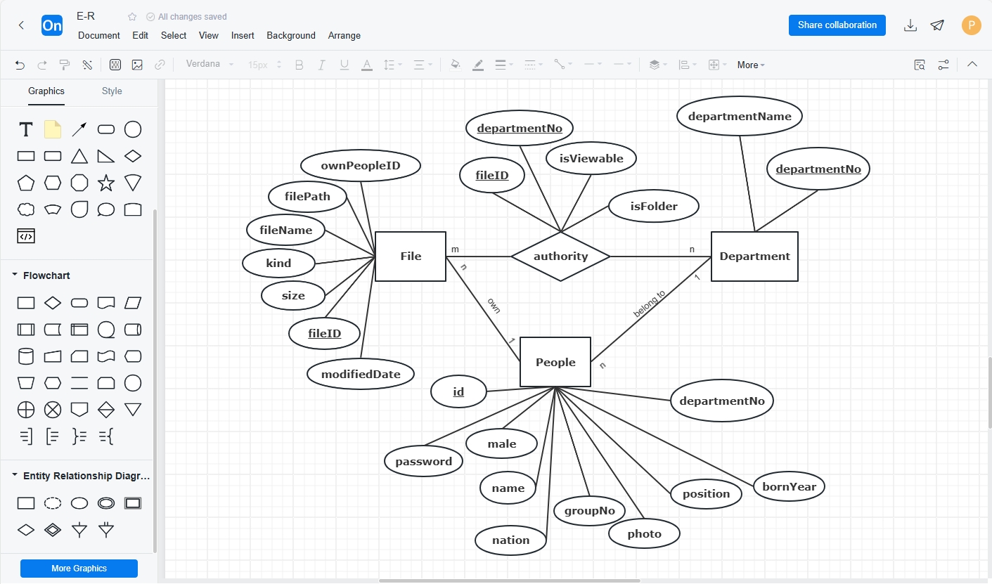
Creating relationships in ProcessOn
With just a few simple steps, you can create an ER diagram. Now you can also try to create an ER diagram .
Click here to create: ProcessOn