UML diagrams can be divided into structural behavior diagrams and dynamic behavior diagrams from different perspectives of the system, and define 10 types of diagrams, including class diagrams, use case diagrams, object diagrams, component diagrams, package diagrams, deployment diagrams, activity diagrams, sequence diagrams, collaboration diagrams, and state diagrams. Today I will share with you a common type of UML diagram - the use case diagram.

A use case diagram is a view that describes system functions and is composed of actors, use cases, boundaries, and the relationships between them. It is a model diagram of system functions that can be observed by external users (called actors). The purpose of a use case diagram is to capture the dynamic aspects of a system. It is used to collect system requirements, including internal and external influences, most of which are design requirements. Therefore, when analyzing a system, its functional use cases should be collected and the actors should be identified.
In simple terms, the purpose of a use case diagram is to: collect system requirements; obtain the appearance of the system; identify external and internal factors that affect the system; and show the interactions between requirements and participants. The essence of a use case is the embodiment of scenario-based thinking and system thinking. The process of drawing a diagram is actually training us to think about problems from the user's perspective, so that we can better understand the business and clearly express the needs.
The use case diagram consists of four elements: actors, use cases, system boundaries, and relationships between actors.
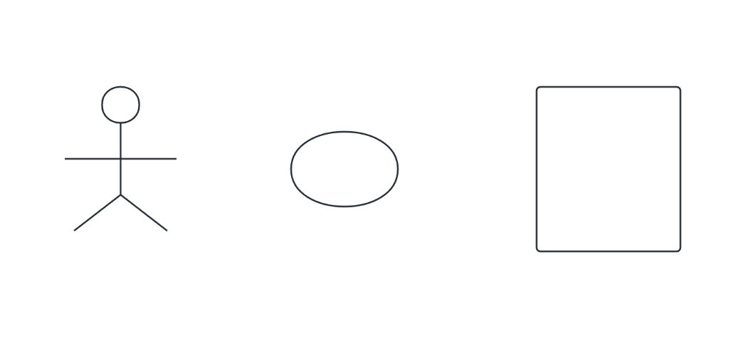
Elements of a use case diagram (from left to right: participant, use case, system name)
Actor : A user, organization, or external system that interacts with an application or system. Represented by a little person.
Use Case : A use case is a system function that is visible to the outside world and describes the services provided by the system. It is represented by an ellipse.
System boundary : The system boundary refers to the boundary between systems. It is represented by a square container + system name.
Relationships between participants : There are three types of relationships in the use case diagram: inclusion, extension and generalization.
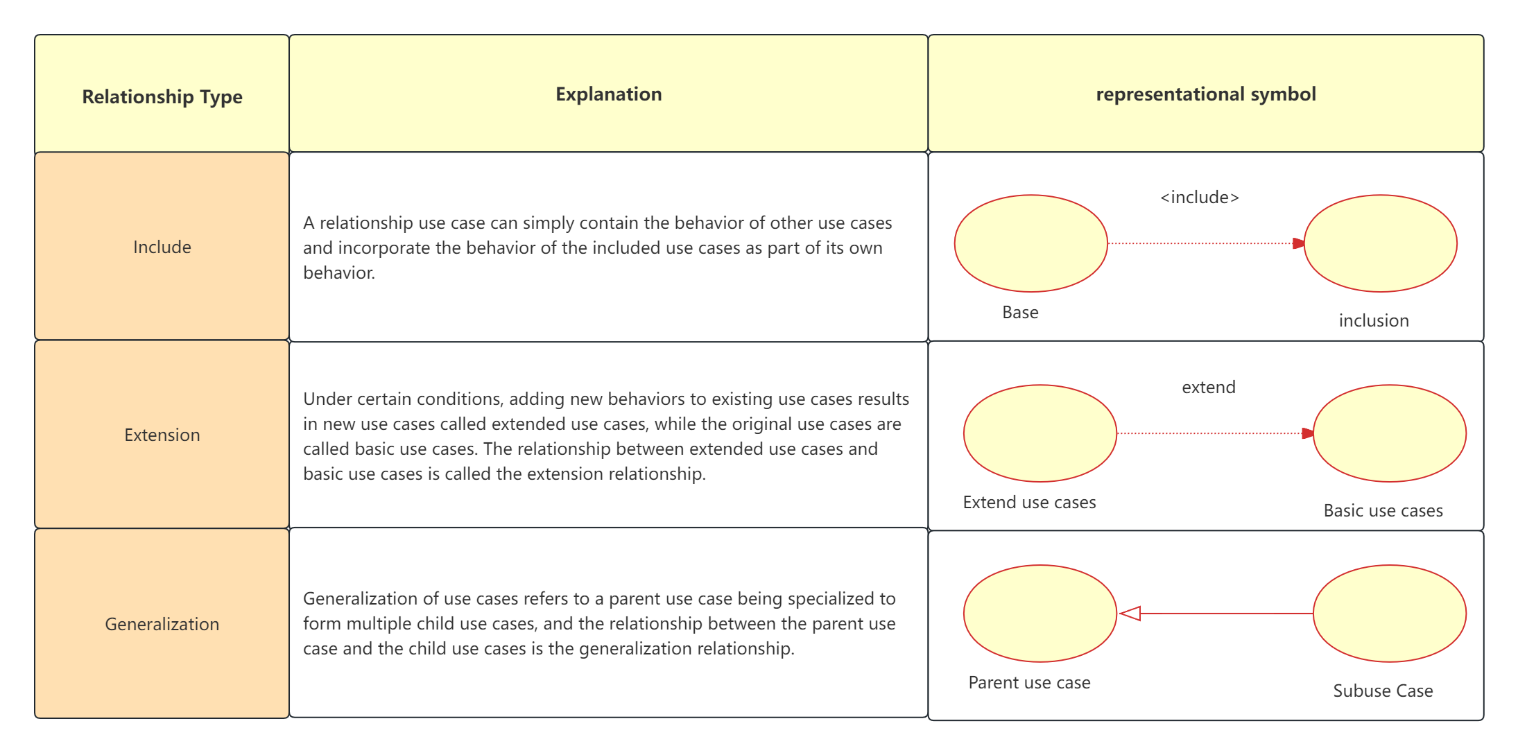
Relationship diagram between participants
ProcessOn supports online editing of flowcharts, mind maps, Gantt charts, prototypes, UML, network topology diagrams, and other graphics. Users can create new content from scratch, or easily edit and modify existing drawing frameworks and case templates. The operation is simple and easy to use.
For each use case, we also need detailed description information so that others can have a more detailed understanding of the entire system. This information is included in the use case specification. The use case specification of each use case should include the following:

UML Use Case Diagram Specification
As a one-stop flowchart tool, ProcessOn supports drawing professional UML diagrams. It can not only draw use cases, but also sequence diagrams, class diagrams, state diagrams/activity diagrams, deployment diagrams and component diagrams, etc., to quickly meet your work needs. The following uses ProcessOn to demonstrate the steps of drawing a UML use case diagram.
Step 1: Create a new flowchart and add a UML diagram or UML use case diagram to the graphics area
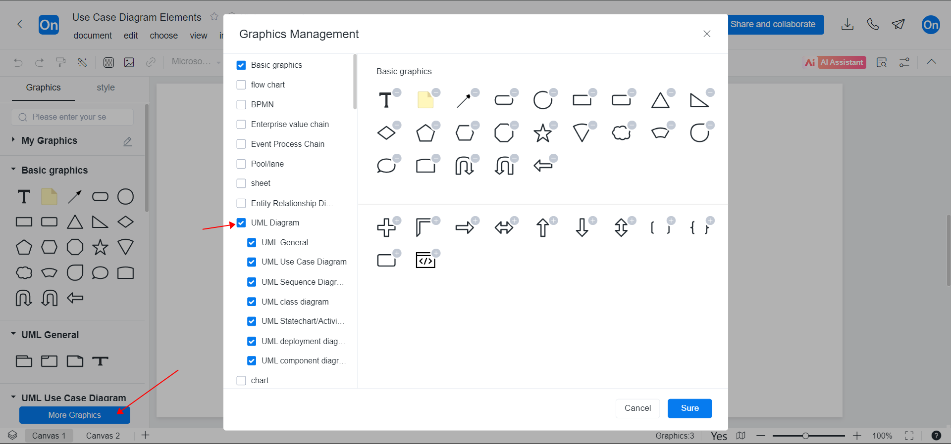
Add UML graphics to the graphics area
Step 2: Drag and drop the UML use case diagram into the graph
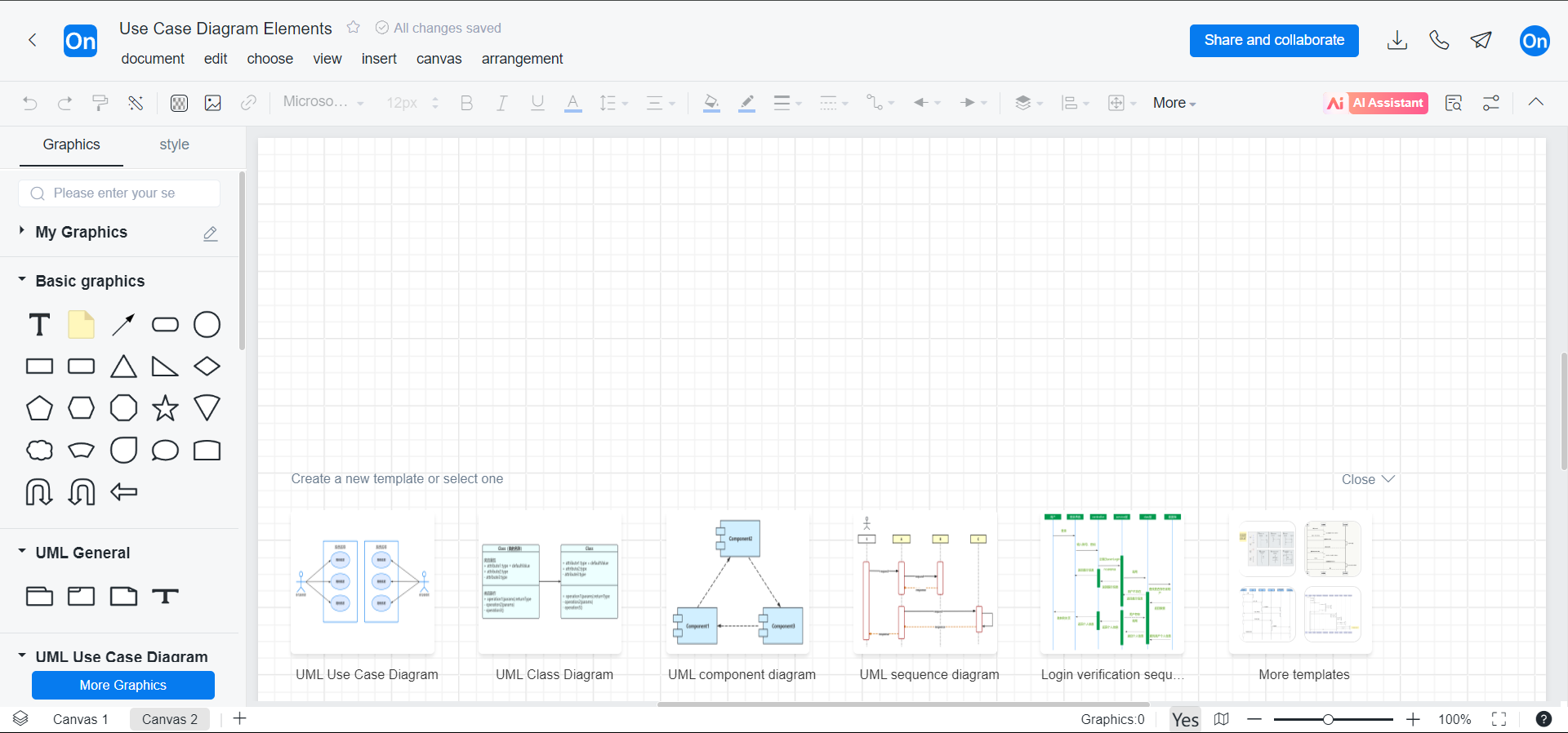
Drag the use case diagram graphic
Step 3: Label content and establish relationships
If you want to make your use case diagram more beautiful, you can fill the graphics with different colors, make the same icons the same size (the reuse function is very useful), keep the upper and lower graphics aligned, etc.
Below are some high-quality use case diagram templates from the ProcessOn community, recommended to everyone.
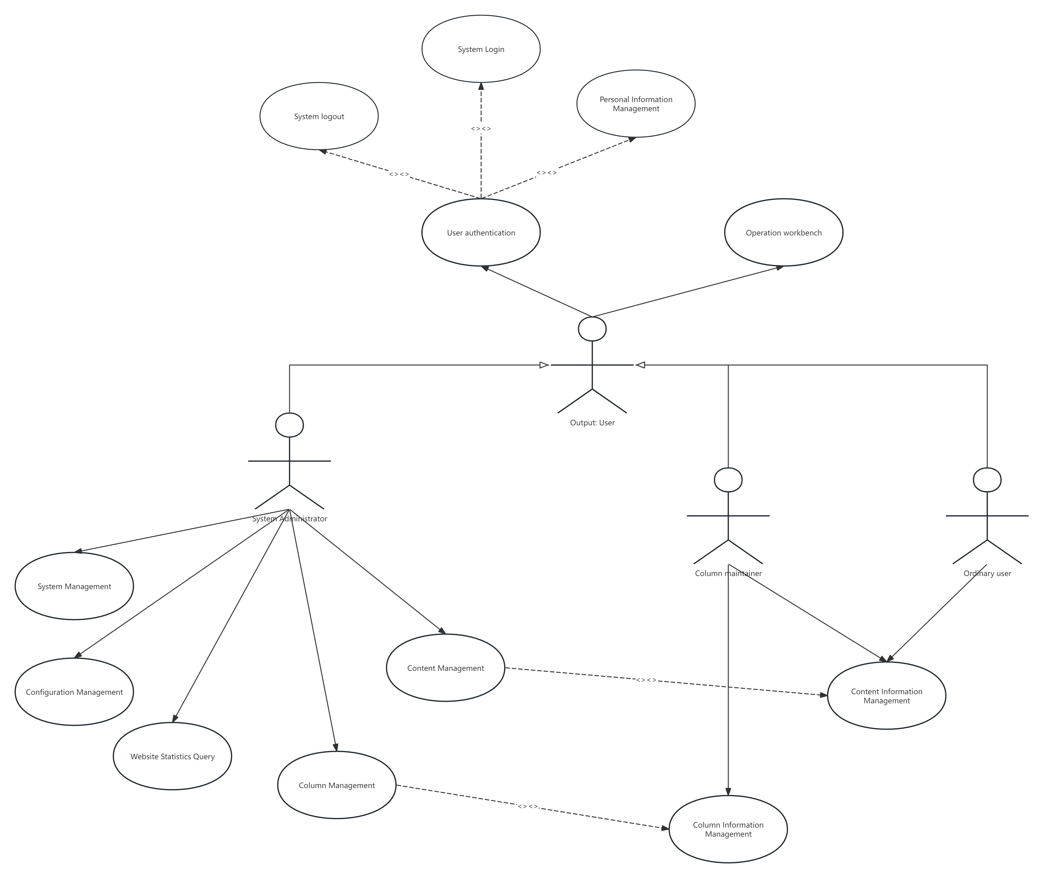
Content Management System Use Case Diagram
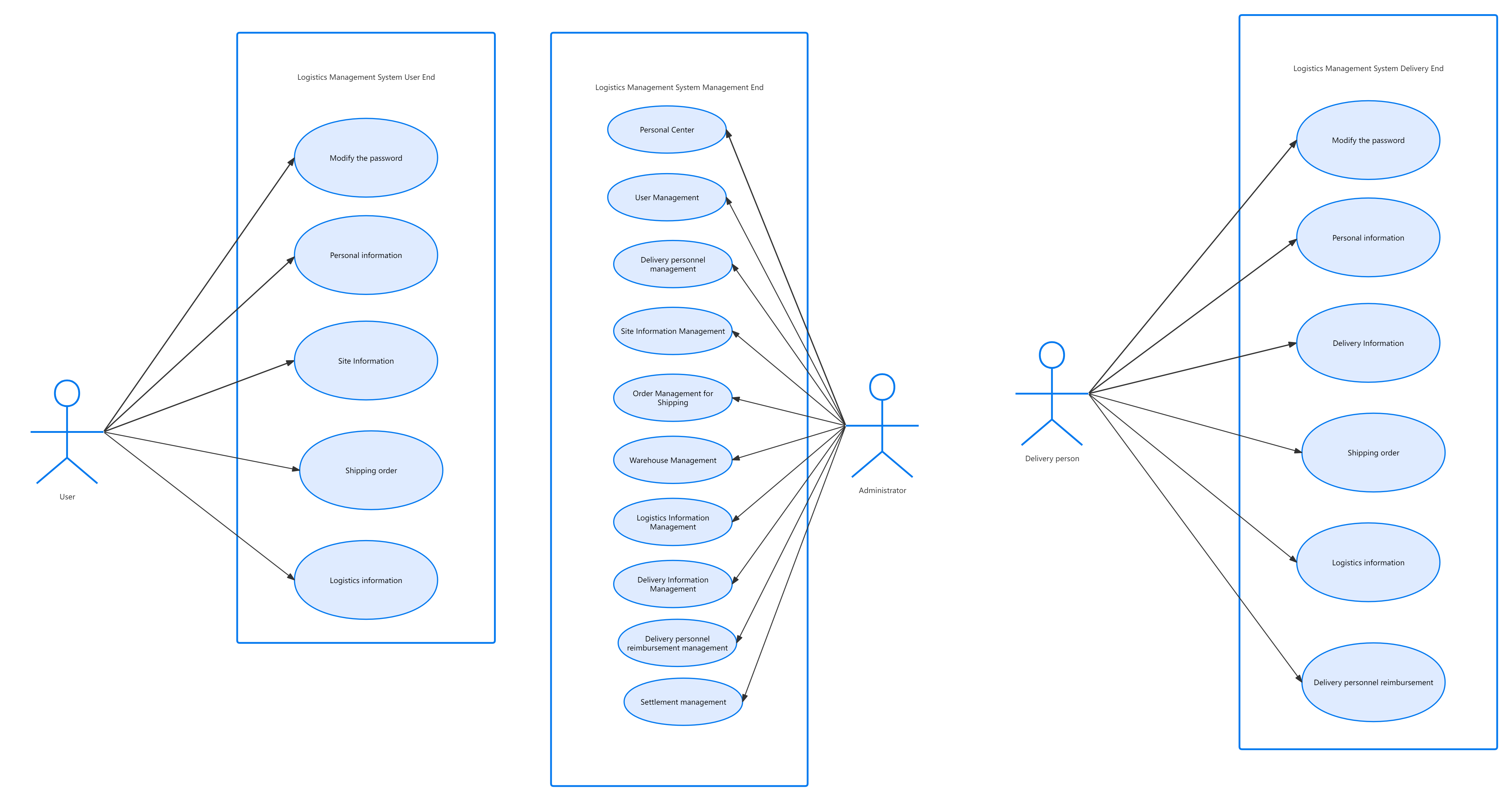
Logistics Management System Use Case Diagram
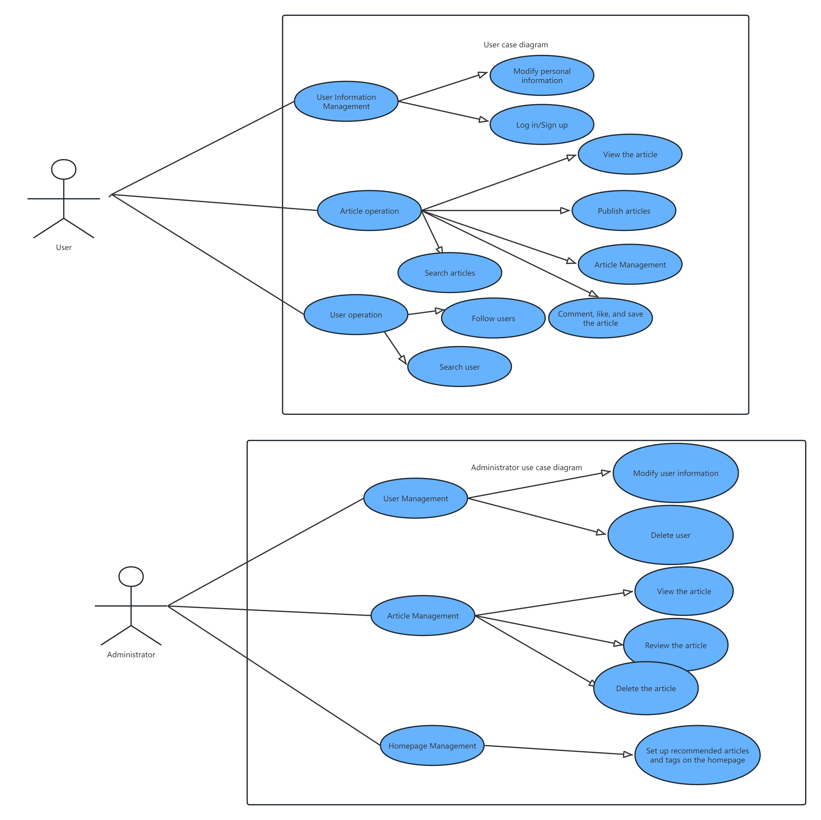
Ticket purchasing system use case diagram
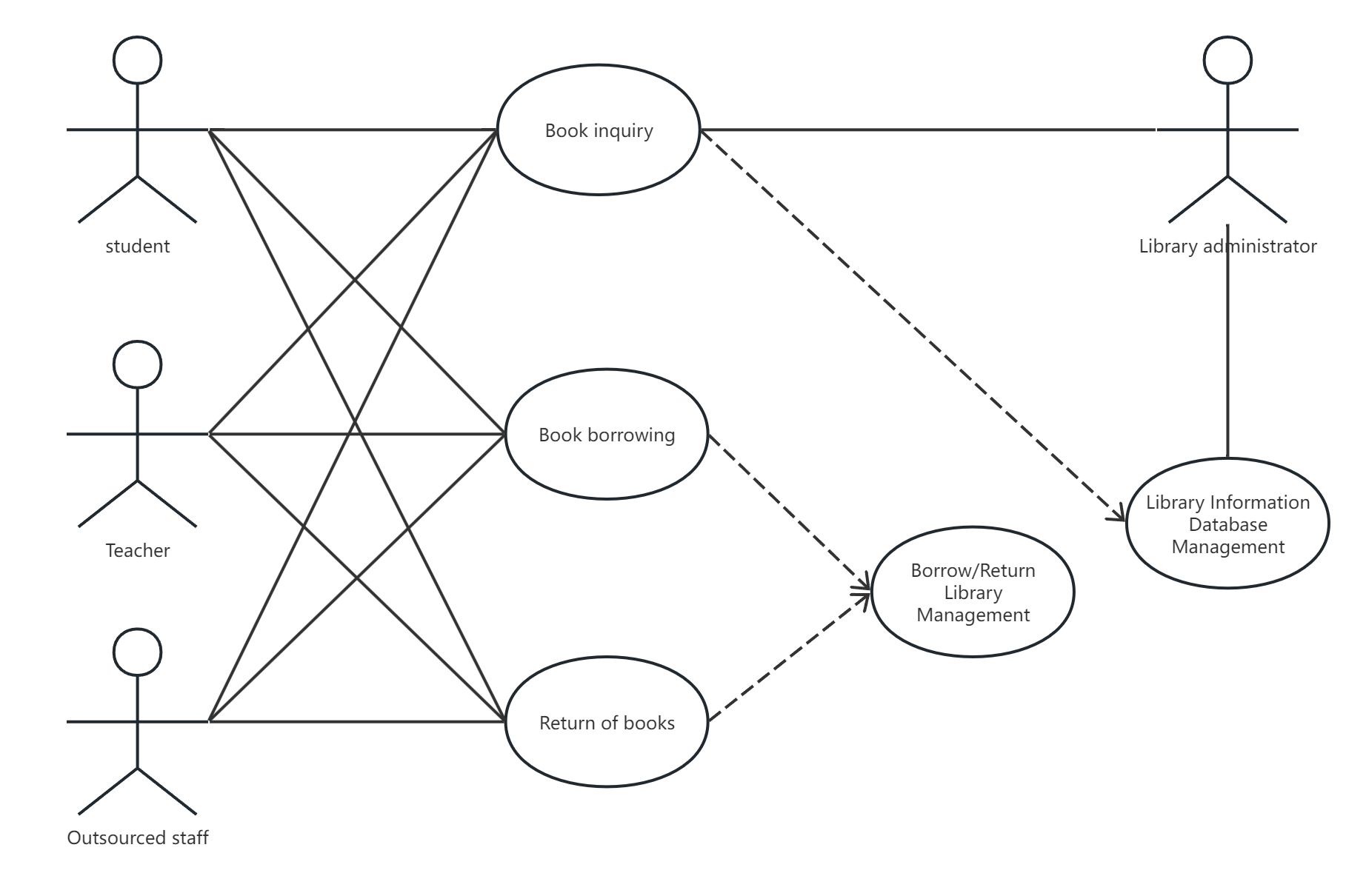
Library loan and return system use case diagram
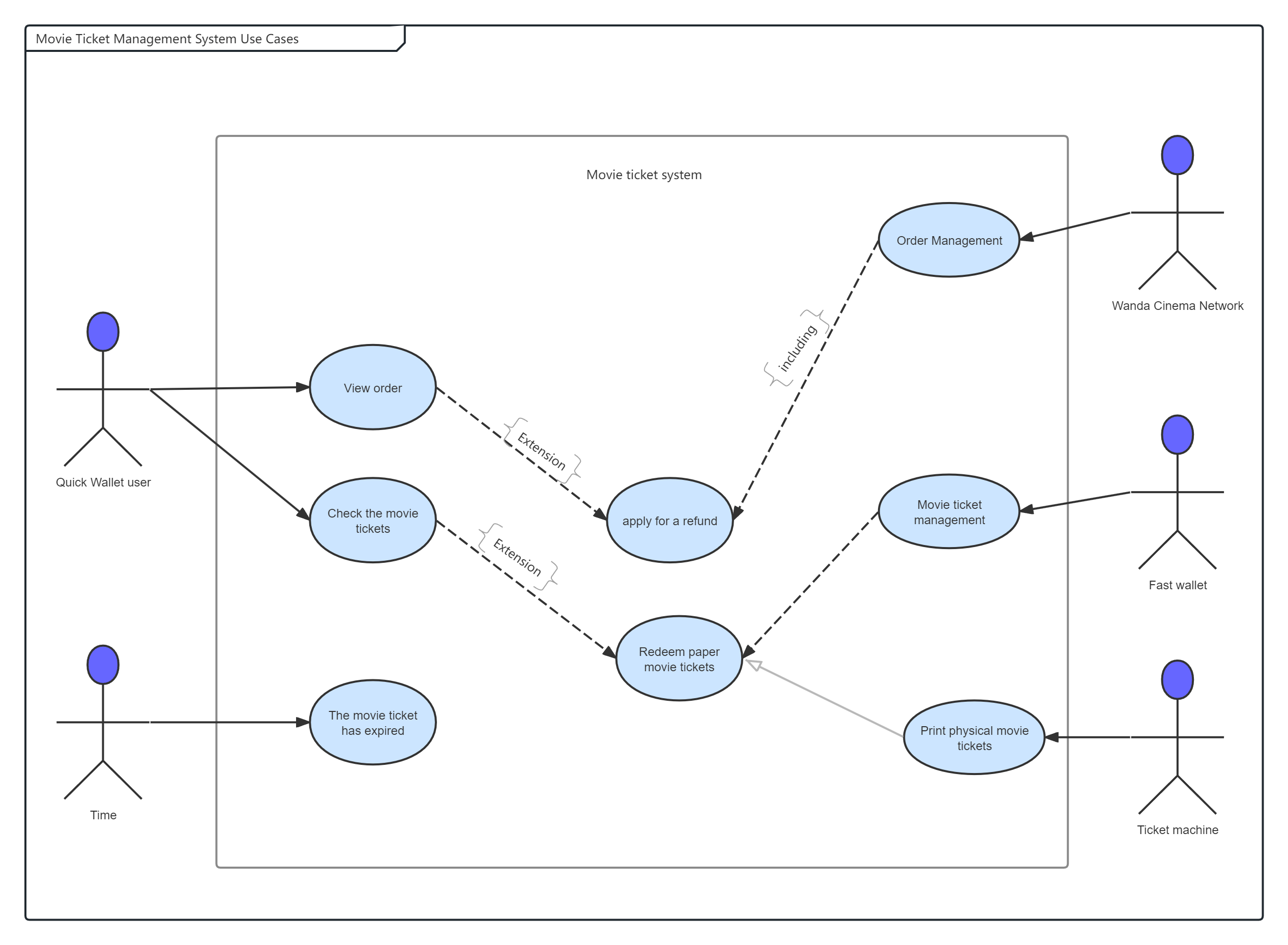
Movie Ticket Management System Use Case Diagram
If you want to know more about UML use case diagrams, ProcessOn template library has a lot of resources. You can search for "use case diagram" to find them. Of course, if you are very professional, you are welcome to publish your diagram to the template library.