

The Use Case Diagram is a view that describes the system functions and is composed of actors, use cases, and the relationships between them. It is observable by external users called actors. A model diagram of system functions. Use case diagrams are often used in the requirements analysis phase.
Before developing a system, the most important task is to obtain user needs. Among the user needs, the most important are the functional requirements of the system proposed by the users. We can use use case diagrams to express user needs visually.

Visual Use Case Diagram
The main elements in a use case diagram include participants, use cases, and the relationships between the elements. In addition, a use case diagram can also contain annotations and constraints.
1. Concept of Participants
Actor is an external entity that interacts with the main system. A participant can be a person, subsystem, other system, etc. outside the system.
Each participant is actually a set of roles. In UML, participants are represented by human-shaped graphics and given a name. For example, the "reader" in the following figure is a participant in the library lending system.
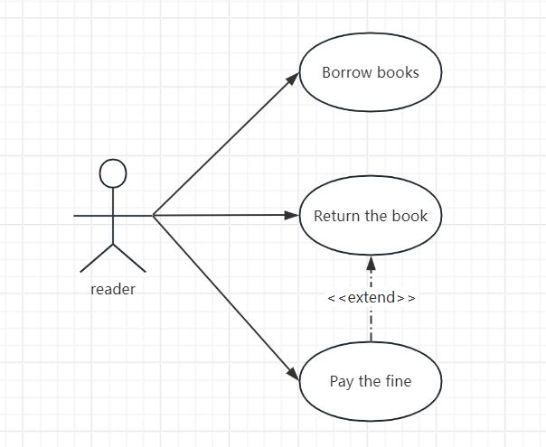
Use Case Diagram Participants
Actors should be outside the system boundaries, not part of the system.
2. How to identify participants
When modeling a use case, determining the participants is the first step in modeling the use case diagram. So, how do we determine the participants of the system ? We can consider the following ideas:
(1) The service objects of the system - such as readers in the library lending system;
(2) People who provide support to complete their work - such as library staff in the library lending system, who need to use the system to help readers complete the tasks of borrowing, returning books, and urging them to return;
(3) System maintainers: people who are responsible for installing, maintaining and managing the system. In this case, the system needs to provide relevant functions to help such people complete the installation, maintenance and management work;
(4) External devices: need to transmit information to or read information from external devices, such as card readers;
(5) Other systems or subsystems: such as the financial system in the borrowing system. The financial system is not a function of the borrowing system, but the borrowing system needs to transmit information to it to complete the overdue fine work;
(6) Time: At a predetermined time, certain events occur automatically, such as automatic backup and scheduled reminders;
(7) Specific events: For example, automatic order acceptance in a food delivery system is driven by order-generating events.
When identifying participants , keep the following in mind:
(1) The participants are outside the system, not part of it;
(2) Participants interact with the system through the system boundary;
(3) Although participants are represented by human icons, participants are not necessarily people. They may also be other subsystems, other systems, time, temperature, and other factors.
3. Relationships among participants
The main relationship between participants is generalization. Generalization is represented by a solid hollow triangle arrow, which points to the more general participant and ends at the "concrete" participant. A generalization relationship is a relationship between a general and a specific (concrete). In a generalization relationship, the abstract description of a participant can be shared by one or more specific participants. The following figure describes the generalization relationship between participants in a library lending system:
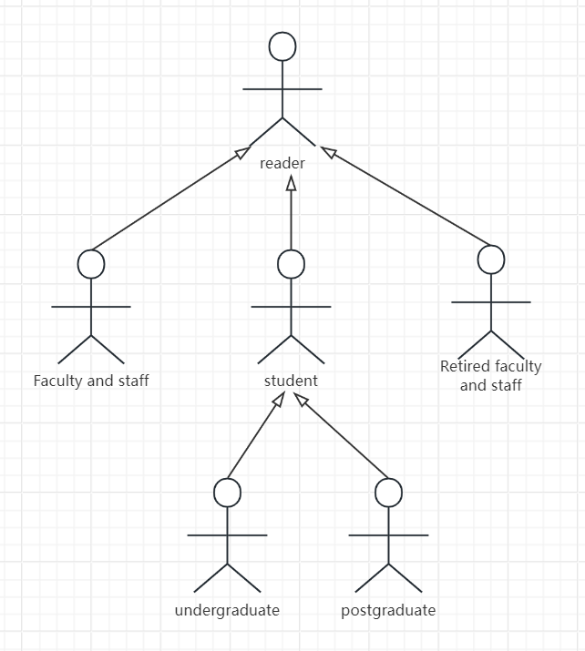
Generalized Relationship among Participants in Library Lending System
retired faculty, etc. below the reader are "specific" actors. Actor generalization can be understood as: "Specific" actors are a kind of "general" actor, such as faculty is a kind of reader. In actor generalization, the use cases that can be executed by "general" actors can also be executed by "specific" ("special") actors.
1. The concept of use case
A use case is a system service or functional unit that a participant can feel. It defines a goal that the system is to achieve. A use case only defines a behavior of the system and does not show the internal structure of the system.
The biggest advantage of use cases is that they describe system functions from the user's perspective. Graphically, use cases are represented by solid ovals, with the name of the use case marked inside or below the ovals:
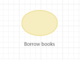
Book borrowing use case
2. Identify use cases
Use cases can be identified by the following points:
(1) What functions does the participant need the system to provide to support his work?
(2) Does the participant need to query certain information in the system?
(3) Do participants need to change certain information in the system, such as create, modify, and delete operations?
(4) Do participants need to be notified of specific events or changes in status occurring in the system?
(5) What external events of the system will prompt the system to perform relevant functions to respond?
(6) Does the system provide relevant functions to help maintenance personnel maintain the system?
3. Key points of use case identification
(1) The identified use cases should reflect the goal of the system, that is, "what to do" rather than "how to do it", that is, the use cases are not the details of the system implementation;
(2) Define use cases from the perspective of participants (users) rather than the system;
(3) Use cases should provide participants with valuable results rather than a collection of actions;
(4) Avoid falling into functional decomposition and step decomposition;
(5) Each participant should have an executable use case, and each use case should be associated with at least one participant.
4. Naming the Use Case
After determining the use cases of the system, you need to name each use case. The naming of the use case needs to describe the goals achieved by the participants from the user's perspective. The following naming methods can be used:
Verb + Object
That is to say, the name of the use case should be in the form of a verb-object phrase, such as choosing a course, borrowing books, ordering goods, and paying with a credit card.
5. Granularity of Use Cases
Use case granularity refers to the degree to which a use case refines or integrates system functions, or the number of system services or functional units contained in a use case. If the use case granularity is too coarse or too large, the use case contains more system functions, and vice versa. If the use case granularity is too coarse, it is not easy to understand the system, and if the granularity is too fine, the use case model will be too large, which will bring difficulties to the design. If the use case granularity is too fine, it may fall into functional decomposition, such as:
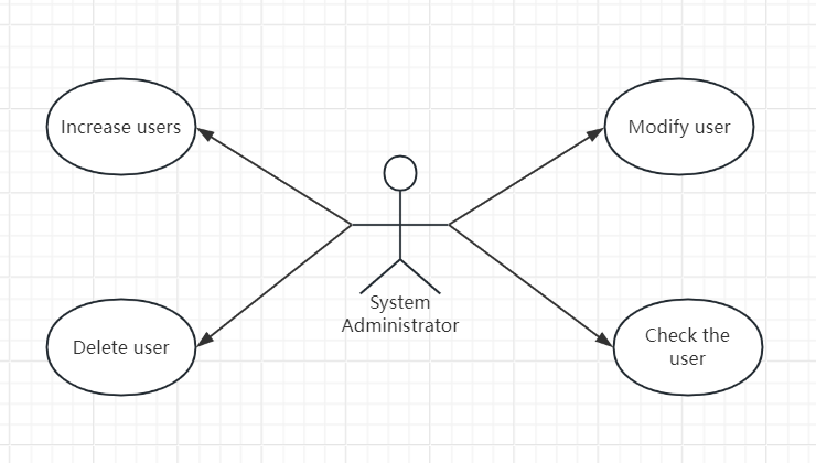
Use case granularity initialization
In fact, many businesses in the system include such operations as adding, deleting, modifying and checking. Doing so does not provide any meaningful goals for users, but instead ignores the user's real purpose.
The above "add, delete, modify and query" is nothing more than user management, which is the real purpose of the participants. It may be better to use the following method to handle the above use case:
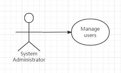
Use case granularity reduction
The use case of managing users reflects a goal or task of the system administrator. If you must add the addition of CRUD, it would be better to express it in the following way.
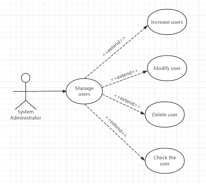
After optimizing the use case granularity
Another common mistake in use case modeling is to treat steps as use cases. For example, the following example seems perfect, but it is obviously treating the operation steps as use cases:
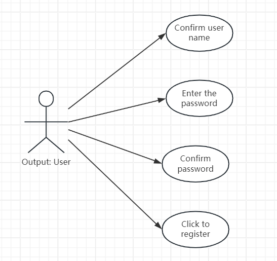
Operation steps as use case error examples
The above steps are nothing more than completing the goal of the user as a participant: registration. Therefore, it should be changed to the following:
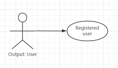
After use case optimization
The third common mistake in use case modeling is to treat system activities as use cases. In the following use case diagram, establishing connection objects, creating command objects, and executing SQL statements are activities within the system, which are not perceived by users, are not the user's purpose, and users do not care about them. Therefore, this use case diagram is inaccurate:
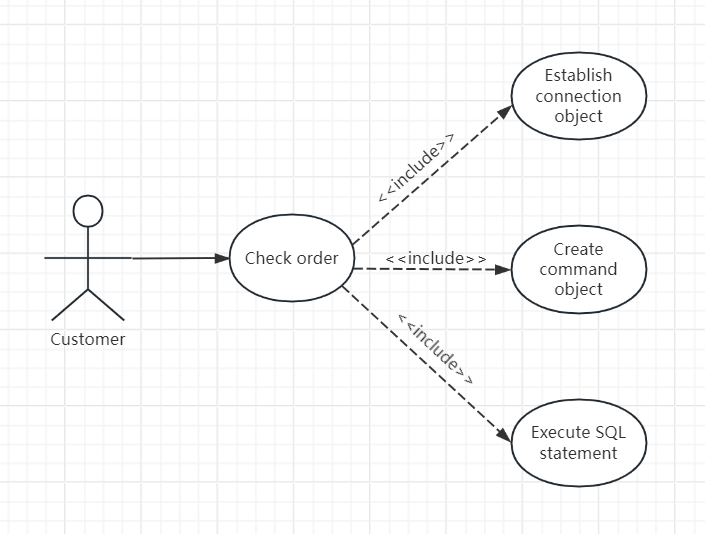
System activity use case error example
The fourth common mistake in use case modeling is to use the system viewpoint to name the use cases.
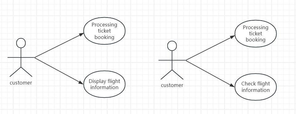
Example of using the system view to name use cases incorrectly
Which of the two use case diagrams above is better? Obviously, the one on the right is better than the one on the left, because the one on the right names the use cases from the user's perspective, while the one on the left names the use cases from the system's perspective, which users will find confusing.
6. Use Case Specification
The use case diagram generally describes the user's functional requirements (the functions or services provided by the system), but each use case must be described in detail so that people know what the use case is going to do. This is the use case specification. In other words, the use case model is essentially composed of the use case diagram and a detailed description of each use case (use case specification).
A use case specification should contain the following:
(1) Identification and name of the use case;
(2) The participants involved in the use case;
(3) A brief description of the use case;
(4) Other related use cases;
(5) Preconditions for use case execution
(6) Basic event flow;
(7) Alternative event flows;
(8) Postconditions for use case execution;
(9) Other information, such as non-functional requirements, design constraints, use case review status, compiler, modification records, etc.
The relationships between use cases mainly include generalization, inclusion and extension.
When multiple use cases have similar attributes or behaviors, we can abstract their commonalities into parent use cases, and other use cases as sub-use cases of generalization relationships, which inherit the attributes and behaviors of the parent use case. The generalization relationship of use cases can be understood as different implementation paths for the same business purpose.
The generalization relationship is represented graphically by a realization with a hollow triangle arrow pointing from the child use case to the parent use case.
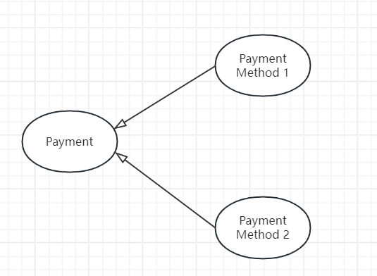
Use Case Diagram Generalization Relationship
In the above example, "Payment Method 1 " and "Payment Method 2 " are sub-use cases of "Payment". The parent use case "Payment" does not provide specific payment methods, but only provides the necessary properties and interfaces for payment, and implements specific payment functions in its sub-use cases.
During the system modeling process, some functions need to be used repeatedly in different business scenarios. These repeatedly used functions can be separated out to form a separate use case, and when executing related functions, the separated common functions can be included in the main process. The inclusion relationship of use cases can describe this situation. In addition, if a basic use case has too many functions, it can also be disassembled into multiple small use cases. The included use case is called the provider use case, and the use case that includes other use cases is called the client use case.
In UML, the include relationship is represented by a dashed arrow with the <<include>> stereotype, with the arrow pointing from the base use case (including use case/client use case) to the included use case (provider use case).
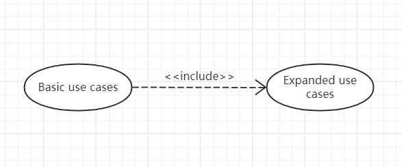
Use case diagram contains relationships
The following is a specific example. In this example, if a reader wants to borrow a book, he needs to execute the book query use case before he can borrow the book. Therefore, the book query use case will be included in the book borrowing use case. At the same time, when a reader wants to borrow a book, he must have logged in to the system and the system has saved his login status before he can borrow the book. Therefore, the identity verification use case will also be included in the book borrowing use case. Book query is a basic function required by readers and a necessary operation process for other functions. Identity verification is not only used when borrowing books, but also when executing functions such as querying borrowing records and paying fines. It is more appropriate to separate identity verification into a use case:
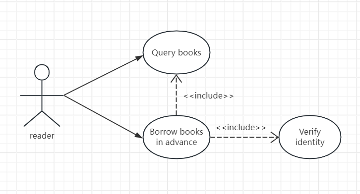
Readers borrow books including relations
The basic use case provides extension points where new behaviors can be added, and the extended use case provides a set of insertion fragments that can be inserted into the extension points of the basic use case.
The base use case only provides extension points without having to know any details of the extended use case.
· A base use case is complete even without extended use cases, which is different from the include relationship.
A use case can provide multiple extension points, and each extension point can appear multiple times.
· Generally, the execution of the basic use case does not involve the extended use case. The functions of the extended use case will only be executed when specific conditions or events occur.
In UML, the extend relationship is represented by a dashed arrow with the stereotype <<extend>>. The arrow points from the extended use case to the base use case.
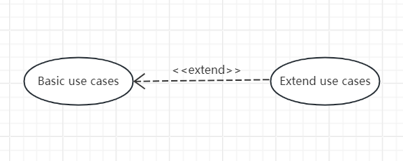
Use Case Diagram Extended Relationship
The following example is a use case diagram fragment in a library lending system:
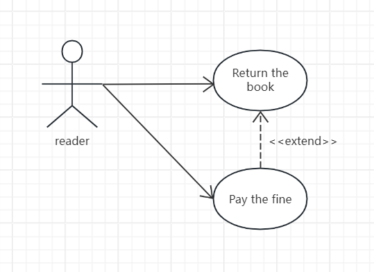
Readers pay fines to extend relationship
In this example, paying a fine is both a basic use case for readers and an extended use case for returning books. As an extended use case for returning books, "paying a fine" will only be executed under the following conditions:
(1) The reader has a record of fines due to overdue books or other reasons, and has not paid them in full;
(2) The reader chooses to pay the fine at the same time as returning the book.
The above is the relevant content about UML use case diagram. All the above use case diagram cases are drawn using ProcessOn.
ProcessOn supports online editing of flowcharts, mind maps, Gantt charts, prototypes, UML, network topology diagrams, and other graphics. Users can create new content from scratch, or easily edit and modify existing drawing frameworks and case templates. The operation is simple and easy to use.
Related reading:
UML diagram complete guide: Master 14 types of UML diagrams in 10 minutes
What is a UML sequence diagram? Attached tutorial and examples
What is UML Activity Diagram? How to Draw an Activity Diagram?