UML use case diagram is one of the commonly used diagrams by product managers and technicians . It is the product of demand analysis. With the help of use case diagram, participants can discuss problems in a visual way, which can reduce a lot of communication barriers. Next, we will discuss and learn about use case diagrams in combination with the use case diagram examples in ProcessOn .
Diagram UML (Unified Modeling Language) is a graphical language for modeling and software system development, which is designed to describe, visualize and document the products of object-oriented development systems. UML use case diagram is a type of UML diagram, which is widely used in the requirements analysis phase of software development. It describes the functions of the system and the interaction between users and the system in a graphical way.
The functions of the use case diagram are : showing the dynamic behavior of the system, clarifying the functional requirements of the system by capturing the interaction between participants and use cases ; collecting internal and external requirements of the system, including design requirements, operational requirements, etc.; showing how different participants interact through use cases, which helps to understand the overall operation process of the system; training product managers to think about problems from the user's perspective, which helps to better understand and express business needs.
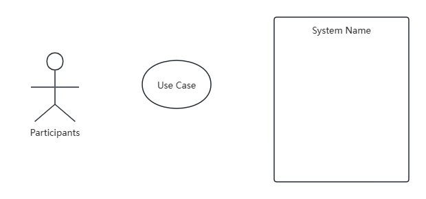
1. Actor:
Actors are external entities that interact with the system, which can be people, other systems, hardware devices, or external services.
Participants are usually represented by a small person icon, located outside the boundaries of the diagram.
Each participant uses the system's functionality through use cases. Each participant can participate in one or more use cases, and each use case can have one or more participants.
2. Use Case:
A use case represents a function or user requirement scenario in the system and describes the services or functions provided by the system to the participants.
Use cases are represented by oval shapes, and their names should concisely describe the functions they represent, such as "User Login", "Submit Order", etc.
Each use case describes a specific operation or interaction process, and describes its basic process, alternative processes, and exception handling in detail through event flows.
3. System Boundary:
The system boundary uses a box to surround the contents of the use case diagram to indicate the boundaries of the system.
Use cases and actors within the system boundary interact directly with the system, while elements outside the system boundary belong to the system environment.
4. Relationship:
Relationships represent the association between use cases and actors, and include the following types:
Association: Indicates the general relationship between actors and use cases, usually connected by a solid line.
Include relationship: It means that one use case includes the functionality of another use case. The included use case is usually a common or reusable function, which is represented by a dotted line with a solid arrow and the word <<include>>.
Extension relationship (Extend): Indicates that a use case can extend the functionality of another use case under certain conditions, represented by a dotted line with a solid arrow + the word <<extend>>.
Generalization relationship: Indicates that one use case is a specialization of another use case, or an inheritance relationship between use cases, represented by a solid line with an empty arrowhead.
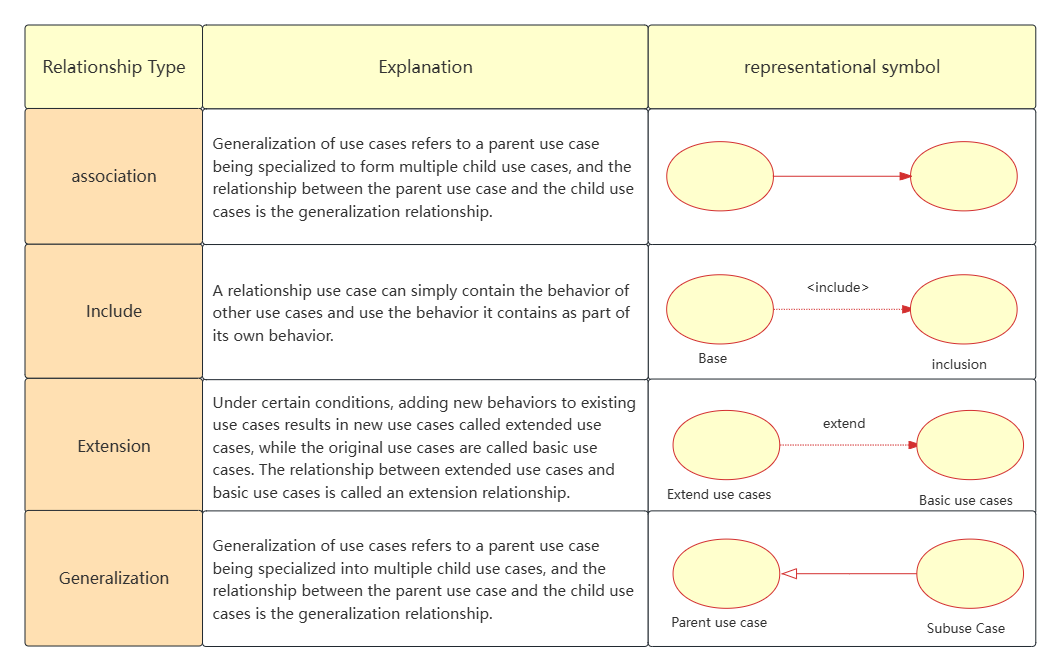
Relationships in UML Use Case Diagram
For each use case, we also need detailed description information so that others can have a more detailed understanding of the entire system. This information is included in the use case specification.
The use case specification of each use case should include the following:

Identify participants:
Identify all external entities that interact with the system, including users, other systems, hardware devices, etc.
Participants can be identified by answering questions such as “Who will use the main functions of the system?”, “Who will need to maintain the system?”
Identify use cases:
For each participant, identify the functionality they want the system to provide.
Use cases can be identified by answering questions such as “What functionality do specific actors want the system to provide?”, “Does the system store and retrieve information?”
Draw the system boundary:
Use boxes to represent the system and its boundaries, making it clear which elements belong inside the system and which belong outside the system.
Building Relationships:
Based on the interaction between actors and use cases, draw relationships such as association, inclusion, extension, and generalization.
Add detailed description:
Add detailed description information to each use case, including event flow, preconditions, postconditions, etc., so that others can better understand the functional requirements of the system.
2. Specific steps
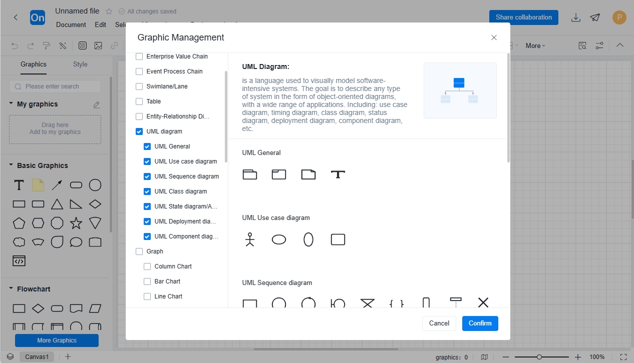
ProcessOn supports drawing professional UML diagrams. It can not only draw use cases, but also sequence diagrams, class diagrams, state diagrams/activity diagrams, deployment diagrams and component diagrams. Professional UML graphics can quickly meet your work needs.
Step 1: Create a new flowchart and add a UML diagram or UML use case diagram to the graphics area
Step 2: Drag and drop the UML use case diagram into the graph
Step 3: Mark the content and establish the relationship. If you want to make your use case diagram more beautiful, you can fill the graphics with different colors, make the same icons the same size, keep the upper and lower graphics aligned, etc.
Below is an example of a use case diagram for your study and learning. If you want to see more UML use case diagrams , go to the ProcessOn template library and search for the keyword "use case diagram". You can find many more. If you encounter a template that you need right now, you can also clone it and use it directly.
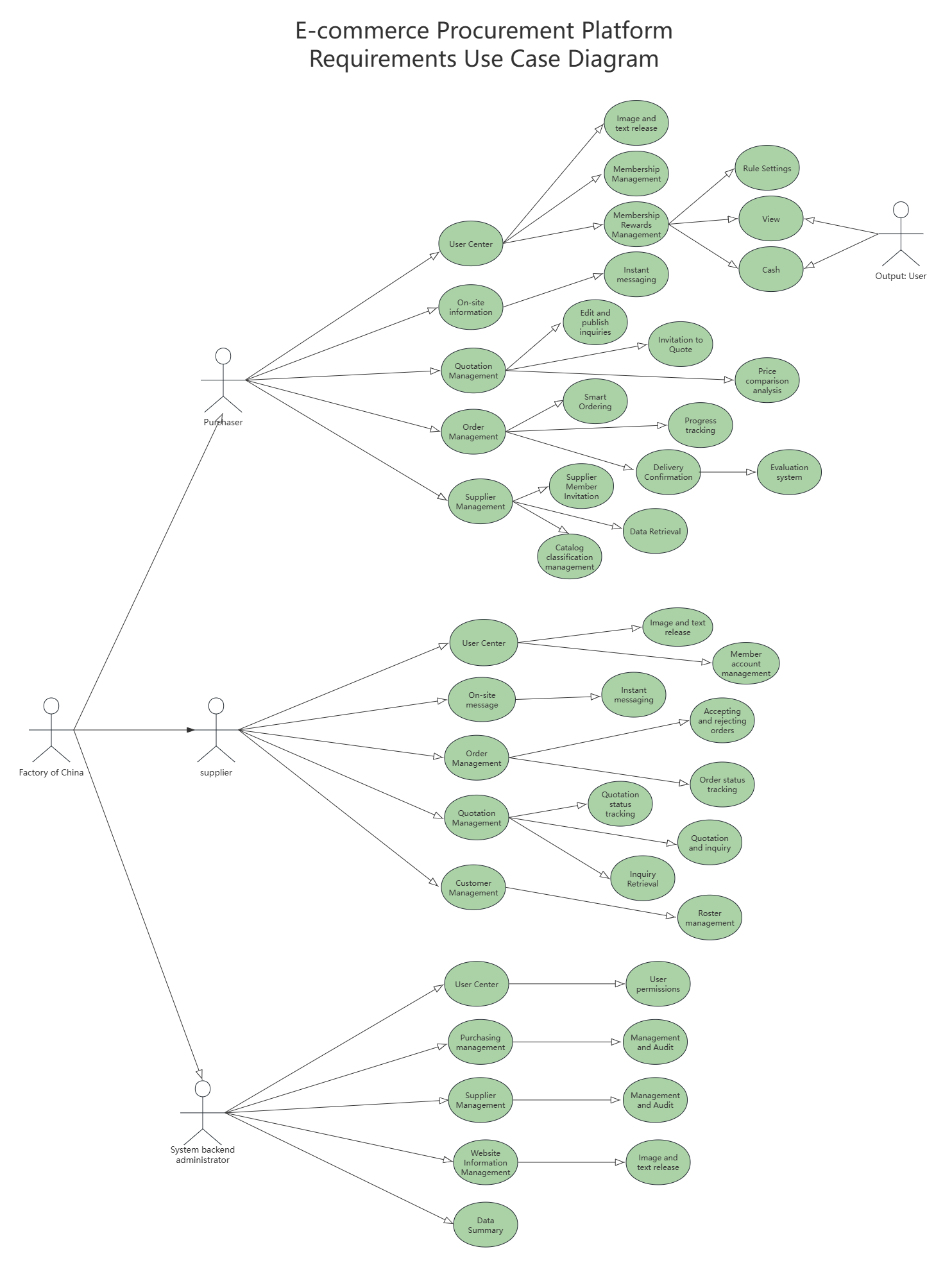
E-commerce procurement platform requirements UML use case diagram 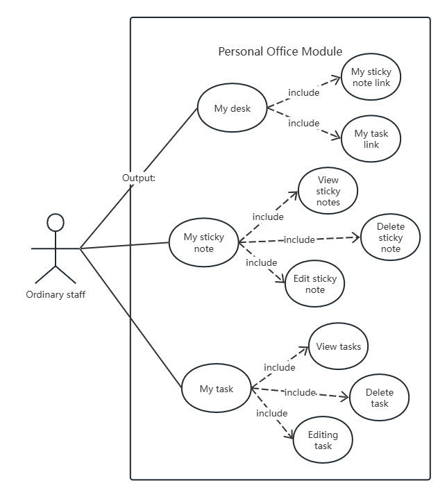
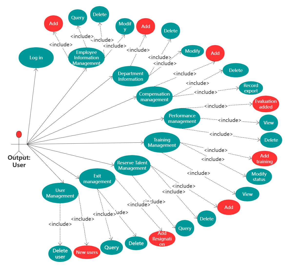
Human Resources Management System UML Use Case Diagram
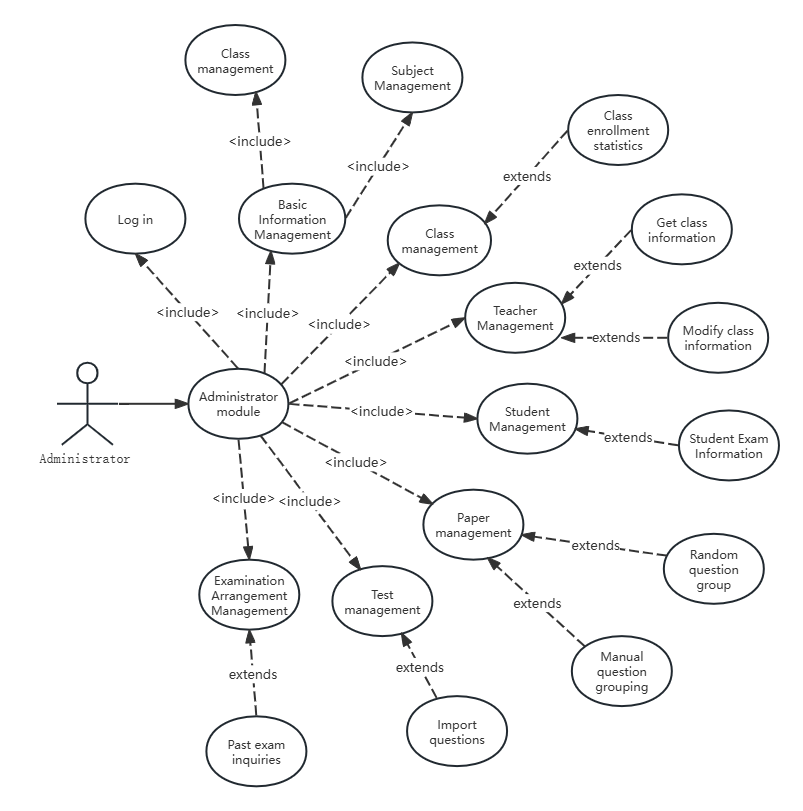
UML Use Case Diagram for Examination System Administrator
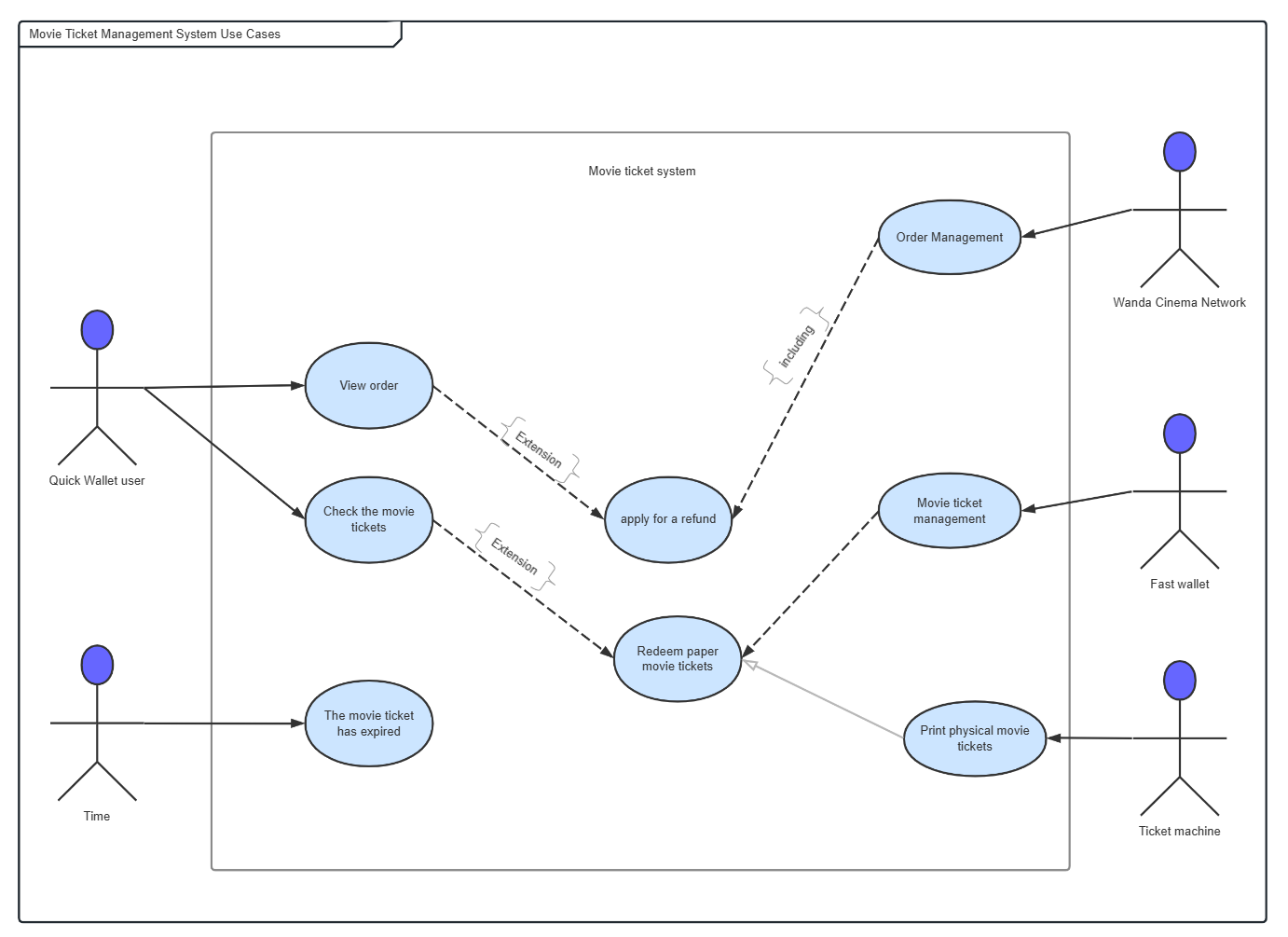
Movie ticket management system use case
As a method of demand analysis, use cases can improve our ability to understand, think and express in demand analysis and product design, and ensure that our output is efficient and accurate . All the above cases are from the ProcessOn template library .