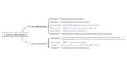
10 Common UML Diagrams
2024-09-09 10:04:55 181 0 Report 0
0

Login to view full content
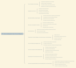
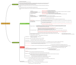
This mind map explores the '10 Common UML Diagrams,' which are vital tools in software engineering for visualizing and documenting system architecture. It categorizes these diagrams into structure-behavior and dynamic behavior diagrams. Structure-behavior diagrams include class, object, component, and deployment diagrams, focusing on the system's static aspects, such as class structures and physical architecture. Dynamic behavior diagrams, like sequence, collaboration, state, and activity diagrams, capture the system's dynamic interactions and workflows. Together, these UML diagrams provide a comprehensive view of both the static and dynamic aspects of system design and implementation.
Other creations by the author
Outline/Content
Structure-Behavior Diagram
Class diagram
Describe the static structure of classes in the system.
Object diagram
The state of multiple objects in the system at a certain moment
Component diagram
A special UML diagram to describe the static implementation view of the system
Deployment diagram
Define the physical architecture of hardware and software in the system
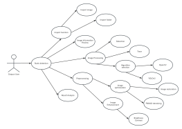
Use Case Diagram
Describe system functions from the user's perspective.
Baotou
A package is a UML structure that allows you to organize model elements such as use cases or classes into groups.
Dynamic Behavior Diagram
Sequence Diagram
The dynamic collaborative relationship between objects, emphasizing the order in which objects send messages, while also showing the interaction between objects.
Collaboration diagram
Describe the assistive relationship between objects.
State diagram
Describe the state-to-state control flow, commonly used for dynamic feature modeling
Activity Diagram
Describes the workflow of the business implementation use case

Collect
Collect

0 Comments
Next page
Recommended for you
More