

In today's highly interconnected world, the network has become the cornerstone supporting the normal operation of all industries. Whether it is information exchange within the enterprise or data transmission around the world, it is inseparable from a stable and reliable network infrastructure. In order to ensure the efficient operation and maintenance of the network system, the network topology diagram has become one of the indispensable tools.
The following content will combine ProcessOn to discuss in detail the various types, application scenarios, drawing methods and cases of network topology diagrams, etc., to help everyone build a more efficient and secure network environment. I hope today's sharing will be useful to everyone~
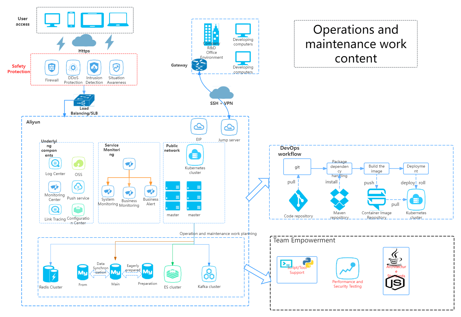
Operation and maintenance work planning-Go to edit
A network topology diagram is a graphical representation of the network structure and the interconnection between devices. It intuitively displays the various nodes in the network (such as computers, servers, switches, routers, etc.) and the physical or logical connections between them.
Network administrators, IT technicians, project managers or educational researchers can present complex network structures in an intuitive graphical way by drawing network topology diagrams, thereby achieving the purposes of visual management, fault diagnosis, security protection, resource optimization and education and training.
There are eight common network topologies, namely star topology, ring network topology, bus topology, tree topology, mesh topology, hybrid topology, cellular topology and distributed topology.
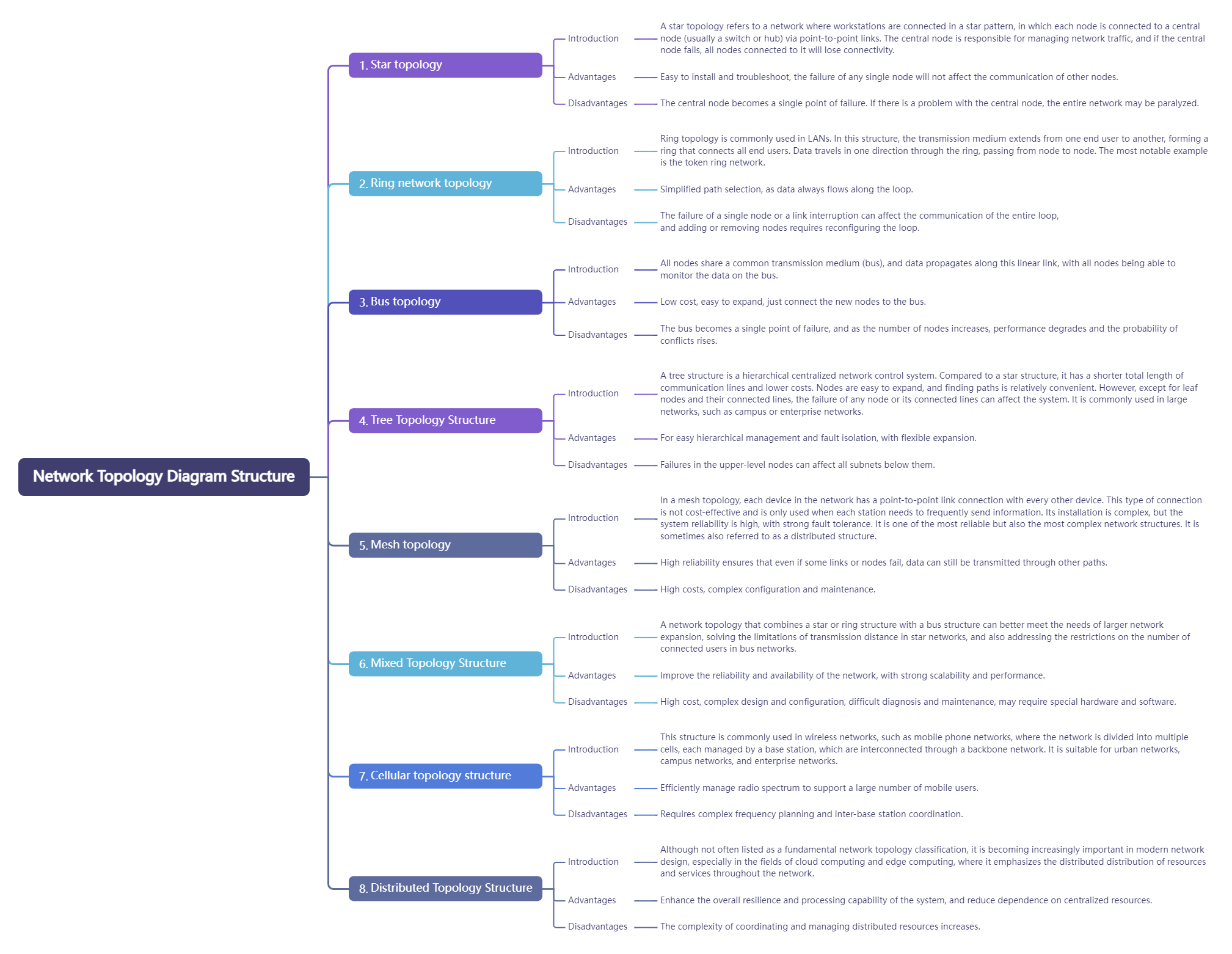
Network Topology Diagram Structure
1. Star topology. Star topology refers to a network in which each workstation is connected in a star shape. In this structure, each node is connected to a central node (usually a switch or hub) through a point-to-point connection. The central node is responsible for managing network traffic. If the central node fails, all nodes connected to it will lose connection.
Advantages: Easy to install and troubleshoot, the failure of any one node will not affect the communication of other nodes.
Disadvantages: The central node becomes a single point of failure. If there is a problem with the central node, the entire network may be paralyzed.
2. Ring network topology. Ring structure is mostly used in LAN. The transmission media in this structure goes from one end user to another until all end users are connected in a ring. Data is transmitted between nodes in one direction in the ring, and information is transmitted from one node to another. The most famous example is the token ring network.
Advantages: Path selection is simplified because data always flows along the loop.
Disadvantages: The failure of a single node or link interruption will affect the communication of the entire ring, and adding new nodes or removing nodes requires reconfiguration of the ring.
3. Bus topology. All nodes share a common transmission medium (bus), data propagates along this linear link, and all nodes can monitor the data on the bus.
Advantages: Low cost and easy to expand by simply connecting new nodes to the bus.
Disadvantages: The bus becomes a single point of failure, and as the number of nodes increases, performance will decrease and the probability of conflict will increase.
4. Tree topology. The tree structure is a hierarchical centralized control network. Compared with the star structure, its total communication line length is short, the cost is low, the nodes are easy to expand, and it is convenient to find paths. However, except for the leaf nodes and the lines connected to them, any node or its connected line failure will affect the system. It is usually used in large networks, such as campus networks or enterprise networks.
Advantages: easy for hierarchical management and fault isolation, flexible expansion.
Disadvantage: Failure of an upper-level node will affect all subnets below it.
5. Mesh topology. In a mesh topology, each device in the network is connected by a point-to-point link. This type of connection is not economical and is only used when each site needs to send information frequently. It is complex to install, but the system has high reliability and strong fault tolerance. It is one of the most reliable but also the most complex network structures. It is sometimes also called a distributed structure.
Advantages: High reliability. Even if some links or nodes fail, data can still be transmitted through other paths.
Disadvantages: High cost, complex configuration and maintenance.
6. Hybrid topology: A network structure that combines a star structure or a ring structure with a bus structure. This topology can better meet the expansion of larger networks, solve the limitations of star networks in transmission distance, and at the same time solve the limitations of bus networks in the number of connected users.
Advantages: Improve network reliability and availability, and have strong scalability and performance.
Disadvantages: Higher cost, complex design and configuration, difficult to diagnose and maintain, and may require special hardware and software.
7. Cellular topology. This structure is usually used in wireless networks, such as mobile phone networks, where the network is divided into multiple cells, each of which is managed by a base station, and the base stations are connected through a backbone network. It is suitable for city networks, campus networks, and enterprise networks.
Advantages: Efficient management of radio spectrum and support for large numbers of mobile users.
Disadvantages: Requires complex frequency planning and coordination between base stations.
8. Distributed topology: Although not often listed as a basic network topology classification, it is increasingly important in modern network design, especially in the fields of cloud computing and edge computing, which emphasizes the decentralized distribution of resources and services in the network.
Advantages: Improve the overall flexibility and processing power of the system and reduce dependence on centralized resources.
Disadvantages: Increased complexity in coordinating and managing distributed resources.
Network topology diagrams play a vital role in many fields and scenarios. Here are some usage scenarios:
1. Network design and planning: When building a new network or renovating an existing network, use the network topology diagram for preliminary design to determine the device location, connection method, redundancy strategy, etc. to ensure the rationality, scalability and stability of the network architecture.
2. Network deployment and configuration: Perform equipment installation, cable laying, IP address allocation, routing configuration and other tasks according to the topology diagram to ensure that the network construction is carried out according to the design intent.
3. Network operation and management: In daily operation and maintenance, the network topology map is an important basis for monitoring network status, diagnosing faults, and optimizing performance. Through the topology map, administrators can quickly locate the source of the problem, adjust the traffic path, and update security policies.
4. Emergency response and disaster recovery: When a network failure or disaster occurs, the topology map helps to quickly identify the affected areas, evaluate the effectiveness of the disaster recovery plan, and guide recovery operations.
5. Education and training: Network topology diagrams are an indispensable tool in teaching, helping students understand complex network concepts and learn network architecture and protocols.
on ProcessOn , for your reference or suggestions:
Step 1: Determine the type of topology you want to draw
Step 2: Create a new network topology diagram, use auxiliary lines to preliminarily plan the general layout of the network according to the business logic, and determine the center point, branch point and device location
Step 3: Drag and drop the device icon onto the canvas
Step 4: Use straight lines, curves or specific line segments to connect
Step 5: Mark information elements and add text notes
Step 6: Adjust line color, thickness, element alignment, etc., remove unnecessary auxiliary and messy elements to make the drawing neat and beautiful
Step 7: Check whether the topology diagram is accurate and logically clear, and complete the drawing
1) Accurately present the logical structure of the network;
2) The network hierarchy is clear and easy to read, and the equipment usage and interconnection status are clear;
3) The information of key network nodes is complete and accurate;
4) Emphasize the key points and choose appropriate node elements;
5) The legend annotations are complete and the topology format is unified;
6) Comply with industrial standards (if it is engineering drawing)
The ProcessOn template library has a lot of network topology diagram templates released by a wide range of professional users. The editor has selected some high-quality content for your reference and to provide some ideas for your drawing.
1. Network topology diagram
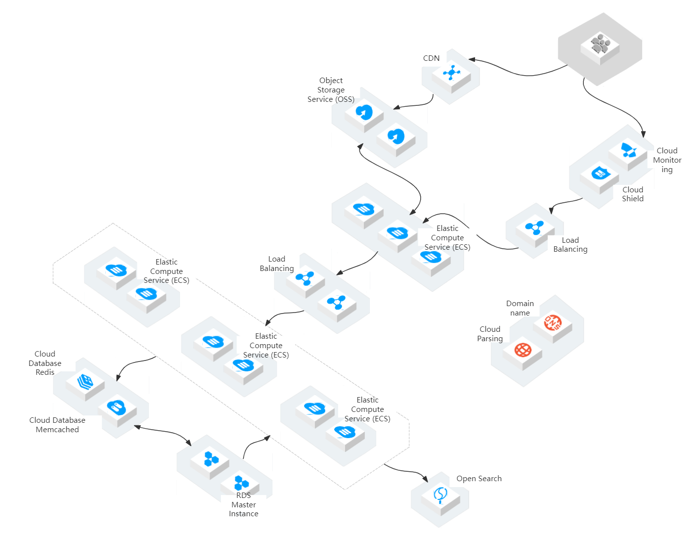
Network topology diagram-Go to edit
2. Smart venue network topology diagram
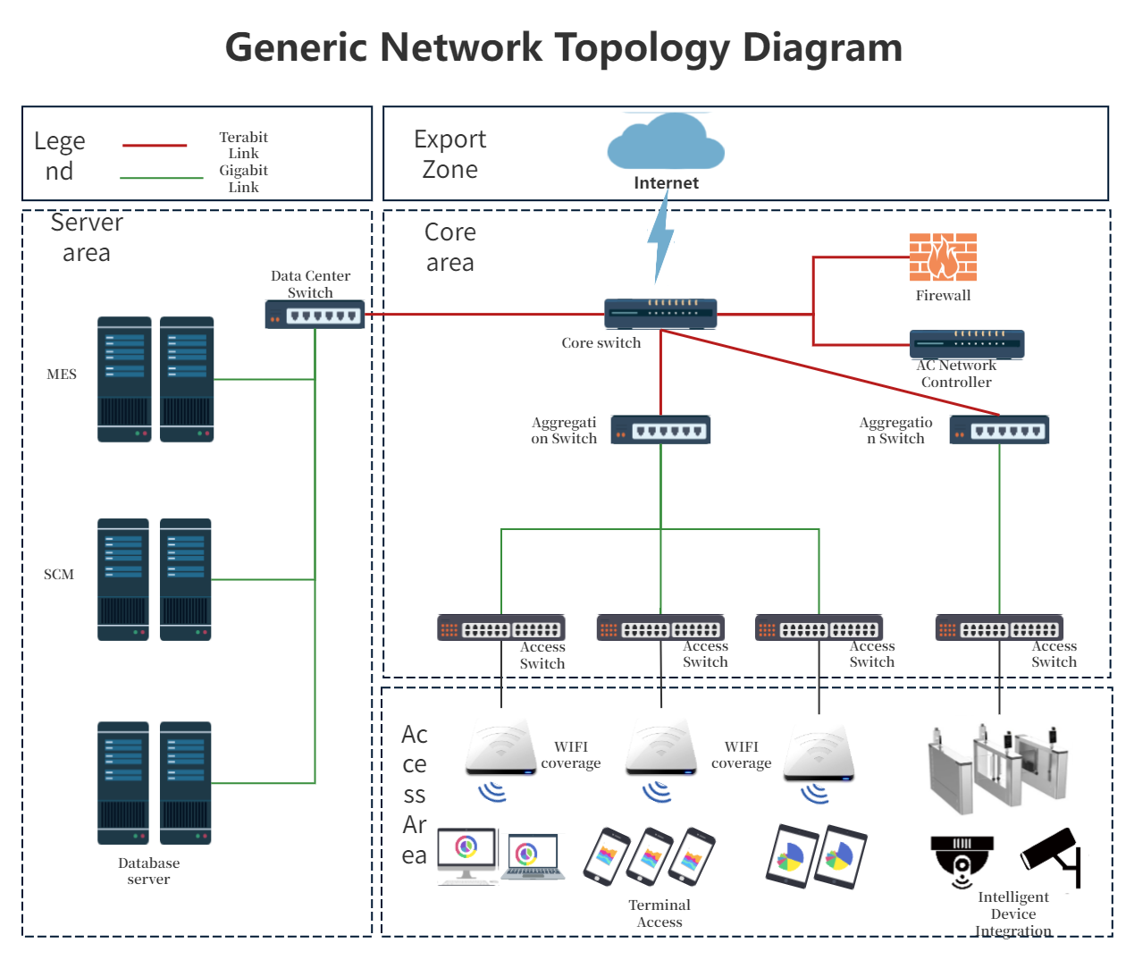
General network topology diagram-Go to edit
3. Network topology diagram
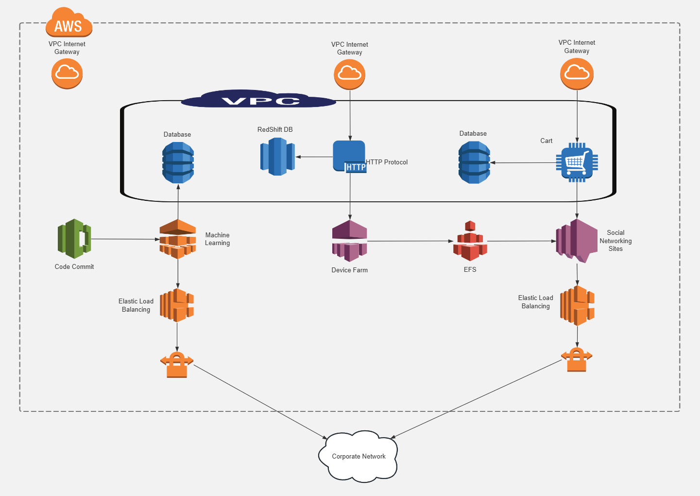
AWS Cloud Computing-Go to edit
The network topology diagram is a core tool in network management and operation and maintenance. It plays an indispensable role for all kinds of network-related personnel. Through reasonable classification and appropriate use, the network topology diagram can greatly improve the efficiency and effectiveness of network management.
The above is a basic introduction to network topology diagrams. All templates come from the ProcessOn template community . If you need to draw a network topology diagram yourself, you can also come to ProcessOn .