

A package is a mechanism for organizing and managing model elements in UML. It organizes conceptually similar and related model elements (including static and dynamic) into a package to form modules with various functions or uses. It can also control the visibility of elements in the package to help people better understand complex systems.
The package diagram consists of the relationships between packages, and the dependencies between the various modules of the system are shown by describing the relationships between packages.
It is similar to a folder in an operating system, so it is also represented in UML using a similar folder symbol:
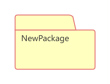
Each package should have a name that is different from other packages in the same hierarchy. Package names can have two forms:
1. Simple Name
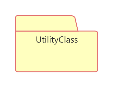
A simple name consists only of the package name string, as in the following example:
2. Path Name
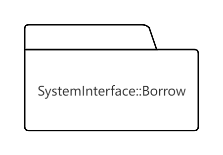
In many cases, a package contains other packages. When using a package in a peripheral, you can use the path name to specify the path of the package. The basic syntax is: external package name:: this package name. The following figure shows that the "Borrow" package is located in the "SystemInterface" package:
A package is a grouping mechanism, so a package can contain any element in UML, such as classes, use cases, interfaces, components, nodes, etc. It can also contain other packages, use case diagrams, collaboration diagrams, sequence diagrams, etc.
There are three main types of element visibility in a package:
1. Public
By adding a "+" sign before an element, it will be visible to all elements that import the package.
2. Private
By adding a "-" symbol before an element, it is indicated that the element can only be visible to elements in the same package.
3. Protected
By adding a "#" symbol before an element, it is indicated that the element is visible to elements in packages that inherit this package.
The following figure shows the three visibility methods of elements in a package:
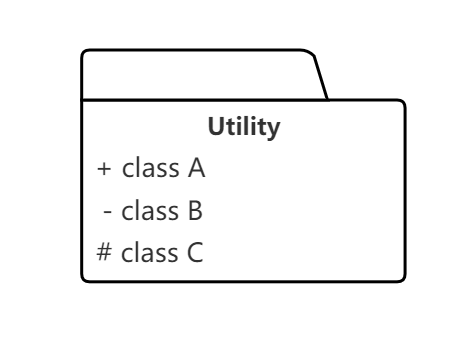
Contains three visibility representation methods for elements
The visibility of the three classes "class A", "class B" and "class C" in the above figure are public, private and protected respectively.
The relationships between packages mainly include dependency relationships and generalization relationships.
1. Dependencies
The dependency relationship between packages refers to the dependency between several elements in two packages. Dependency is represented by a dotted arrow, which points from the dependent package to the dependent package. The dependency relationship between packages can be generalization, implementation, import, etc. The following figure shows the dependency relationship between two packages:
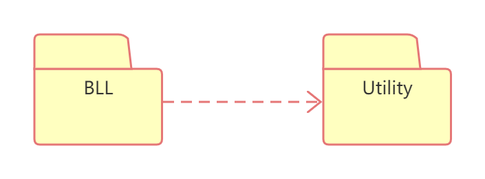
An import dependency allows an element in one package to access an element in another package. This can be represented by adding the <<import>> stereotype to the dotted arrow. Import dependencies are not transitive.
2. Generalization relationship
The generalization relationship between packages is similar to the generalization relationship between classes. This generalization relationship between packages means that special packages can replace elements in general packages and add new elements. In fact, the generalization between packages is also a dependency relationship.
The following diagram shows some stereotypes of packages, represented by different graphics or symbols:
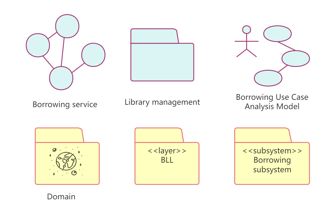
Package Stereotype
In the above figure, from top to bottom and from left to right, they represent Business Analysis Model, Business System, Business Use Case Analysis Model, Domain Package, Layer and Subsystem. You can select the corresponding stereotype of the package as needed to quickly identify the role of the package.
The following principles can be followed in actual modeling:
1. Reuse equivalence principle
Try to put the same type of reusable model elements into one package, and do not mix reusable model elements and non-reusable model elements into the same package.
2. Principle of common reuse
Put multiple model elements to be reused in the same application into the same package to reduce dependencies between packages and improve package independence.
3. Common closure principle
Put model elements that may be modified and maintained at the same time into a package to facilitate future maintenance and upgrades.
4. Non-circular dependency principle
The dependencies between packages should not form a cycle: that is, do not allow A to depend on B, B to depend on A, or multiple packages to form a circular dependency.
Strictly speaking, package diagrams are not real UML diagrams, but they play an important role in model element classification, model structure, and program namespace. In the actual modeling process, you can use the following methods to draw package diagrams:
1. Analyze the model elements of the system and put the conceptually or semantically similar model elements into one package;
2. Identify the visibility of each element in the package;
3. Determine the dependencies between packages;
4. Draw the package diagram and optimize it.
In ProcessOn, you can create a package diagram in a UML diagram file, or you can create a package diagram by adding graphic elements involved in package diagram creation to a flow chart.
1. Create a package
Simply drag the "Package" element in the UML general diagram from the graphic component area on the left side of the editor to the blank area on the right side of the editor to complete the creation of the package.
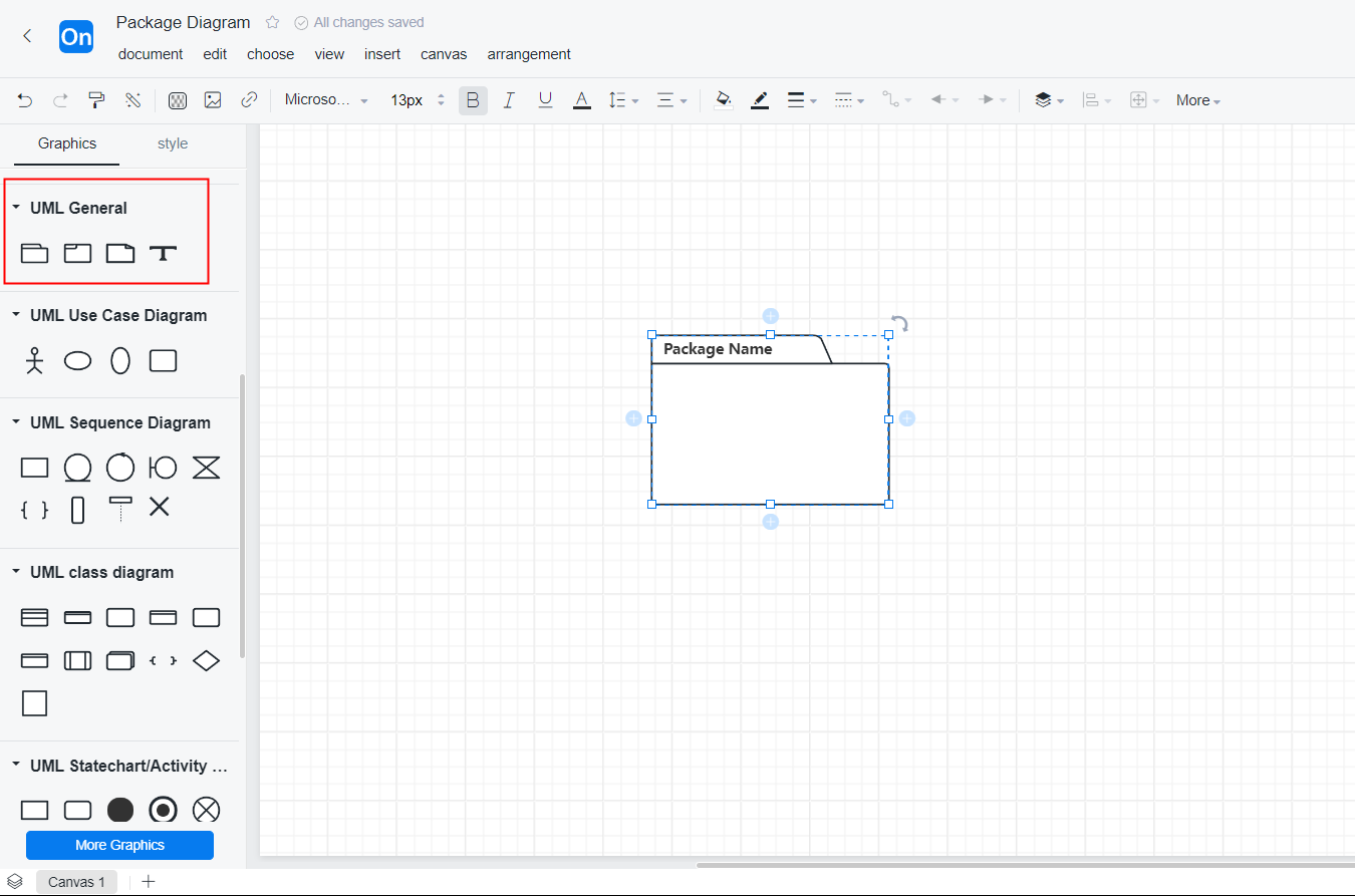
Creating a Package Using ProcessOn
2. Package renaming
Click "Package Name" on the package icon to rename the package.
3. Add elements to the package
When drawing, users can directly drag the graphics from the graphics component area on the left side of the editor to the blank area of the editor to complete the creation of the graphics. Then, after selecting the graphics, you can set the graphics-related properties through the toolbar at the top of the editor and the tool panel on the right.
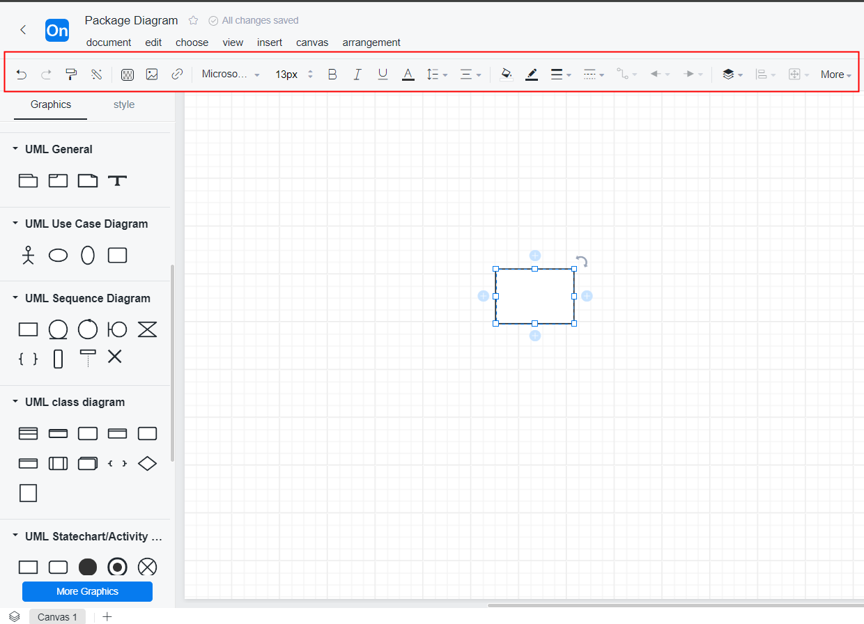
Adding elements to a package
4. Add connections between packages
To draw a connection, use the shortcut key "L", or drag the "straight line" element from the basic graphic in the graphic component area on the left to the blank area of the editor, or directly move from one end of a graphic to another to get a line. If you want to add a dependency connection, select the "dependent package", click one end of it, hold down the left mouse button to the "dependent package", and release the mouse to complete the establishment of a dependency relationship.
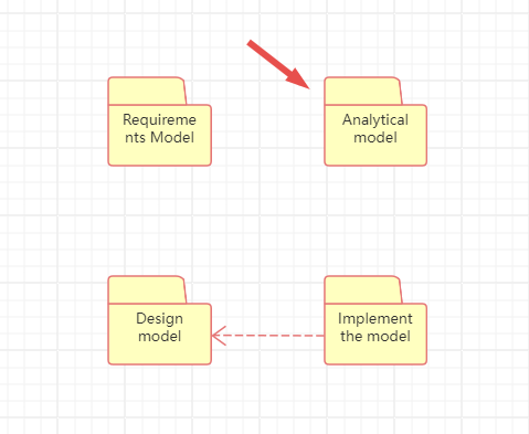
Adding connections between packages
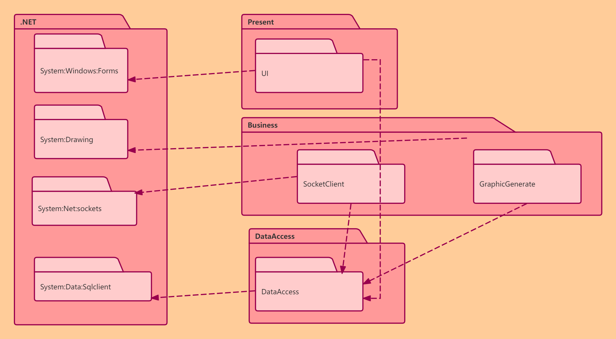
The following are two examples of package diagrams to illustrate the specific usage of package diagrams.
The first example reflects the organization of model elements during the modeling process, using packages to organize various models according to the stages of system analysis and design.
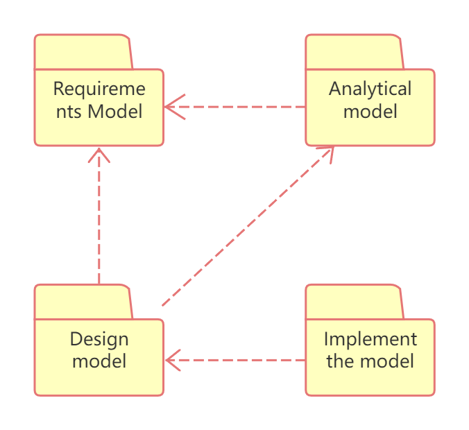
Organization of model elements during modeling
The second example describes the organization of various elements in system development. UI contains various user interfaces used, BLL contains various classes or interfaces for business logic processing, DAL contains classes related to the data access layer, and Common stores some components or classes shared by various modules of the system.
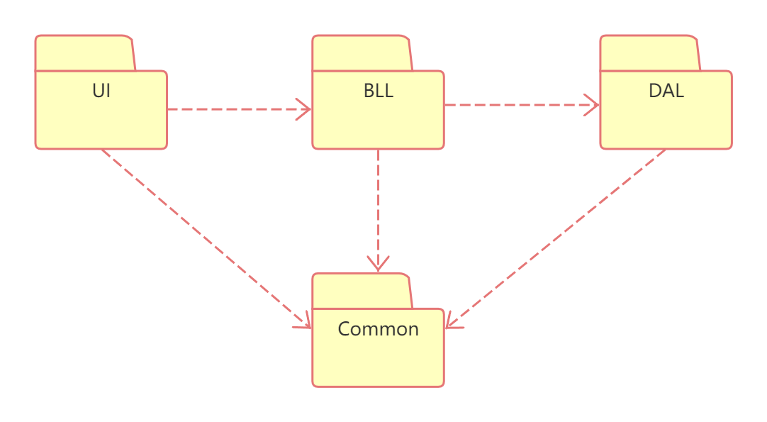
Organization of elements in system development