In the process of software development, as the scale and complexity of projects increase, effective design and documentation tools become essential. As a standardized modeling language, Unified Modeling Language (UML) provides developers with a powerful way to describe, build and visualize software systems. Among them, UML class diagram, as one of the core tools of object-oriented design (OOD), plays a pivotal role.
UML class diagrams graphically display the classes in the system, the relationships between them, and the internal structure of the classes, such as attributes (fields) and methods (functions). These diagrams not only help developers understand the overall architecture of the system, but also promote communication and collaboration in teamwork, ensuring that all members have a common understanding of the design. Today we will learn about UML class diagrams.
What is a class diagram? What are the drawing rules for class diagrams? How to draw a class diagram? To facilitate your learning, the editor has summarized it here. I hope that after reading it, you can have a basic understanding of class diagrams.
The class diagram is mainly used to reflect the structure (attributes, operations) of the class and the relationship between the classes. It describes the structure of the software system and is a static modeling method. Class diagrams are used to describe meaningful concepts in the system, including specific concepts, abstract concepts, implementation concepts, etc., which are abstractions of things in the real world. The main function of class diagrams is to model the vocabulary of the system, model simple collaboration, and model logical database models.
In general, class diagrams are composed of two parts: the relationship between classes. The definition of a class is shown in the figure below. It is mainly composed of three parts: class name, class attributes, and class methods, corresponding to the three partitions in the figure.
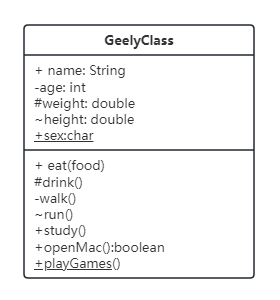
Class name : The top rectangle in the figure is the class name. If the font is italic, it means it is an abstract class.
Class properties : the area below the class name
Class methods : the lower part of the diagram
* Symbol explanation : The "+", "-", and "#" in front of properties and methods indicate access levels. These symbols are explained below.
+: public, visible to all classes
-: private, private, only available to the class itself
#: protected, visible to descendants of this class
~: package, only visible to other classes declared in the same package
=: indicates the default value
Underline: static
Italic: abstract (note that you can also use two angle brackets to indicate abstraction, for example - <<I am an abstract class or interface>>)
The method name/variable name comes before the colon (distinguished by whether there are brackets or not), and the return parameter/variable type comes after the colon (distinguished by whether there are brackets or not). If there is no colon, it means the method returns void (some people also use: void to indicate return void).
The relationships between classes mainly include six types of relationships: generalization (inheritance), dependency, association, aggregation, combination and realization. They are explained one by one below.
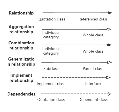
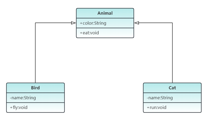
1. Generalization
relationship is an inheritance relationship. The subclass inherits all behaviors and attributes of the parent class. The subclass can add new functions or override the parent class functions. Representation method: hollow triangle + solid line, with the arrow pointing to the parent class
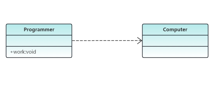
2. Dependencies
A dependency relationship means that one class uses (depends on) the services or information of another class. When a change in one class affects another class, a dependency relationship exists between two classes. Generally speaking, dependencies are always one-way and there should not be two-way dependencies. Representation method: angle brackets + dotted line
3. Relationship
An association is a kind of ownership relationship, which enables one class to know the properties and methods of another class. It reflects a strong dependency relationship between different classes, such as me and my friend. This relationship is stronger than dependency, and there is no contingency in dependency. The relationship is not temporary, but generally long-term.
Associations are divided into unidirectional or bidirectional associations, and can also have multiplicity (one-to-many). Bidirectional associations can have two arrows or no arrows, and unidirectional associations have one arrow. Representation method: angle brackets + solid line, with the arrow pointing to the owner

4. Aggregation
Aggregation is a type of association relationship, which indicates a "weak" "ownership" relationship. It is a relationship between the whole and the part, and the part can exist independently without the whole. For example, the relationship between the car and the tire is a relationship between the whole and the part, and the tire can still exist independently without the car. Representation method: hollow diamond + solid line, the diamond points to the whole

5. Combination relationship
A combination relationship is also a type of association relationship. It is a stronger relationship than an aggregation relationship. It is a relationship between the whole and the individual, but the individual cannot exist independently without the whole. For example, the relationship between a company and a department is a relationship between the whole and the part. Without a company, there would be no department. It requires that the object representing the whole in a normal aggregation relationship is responsible for the life cycle of the object representing the part. Representation method: solid diamond + solid line

6. Implementation relationship is a relationship between a class and an interface, indicating that the class is the implementation of all features and behaviors of the interface. Representation method: hollow triangle + dotted line
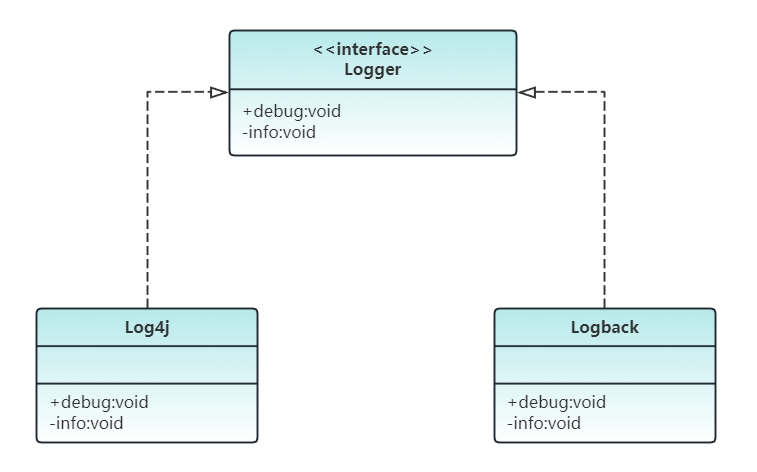
In order to help you better understand the six relationships between classes, the following examples are used to assist you in learning and digesting them.
1. Automobile Class Diagram
Automobile Class Diagram Description:
The relationship between car, car and bicycle is "realization", which is represented by a dotted line with a hollow arrow;
The relationship between cars and SUVs is a generalized relationship, represented by a solid line with a hollow arrow;
The relationship between the car, the engine and the tires is a "combination", which is represented by a solid line with a solid diamond arrow;
Students need bicycles to go to school, and have a "dependent" relationship with bicycles, which is represented by a dotted line with an arrow.
There is an "aggregation" relationship between students and classes, which is represented by a solid line with a hollow diamond arrowhead;
The relationship between students and ID cards is "associated", which is represented by a solid line with a pointed arrow;
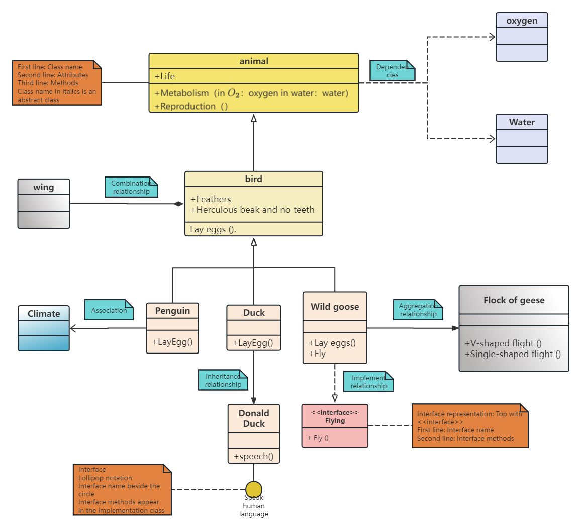
2. Animal UML Class Diagram
3. Students surfing the Internet UML class diagram
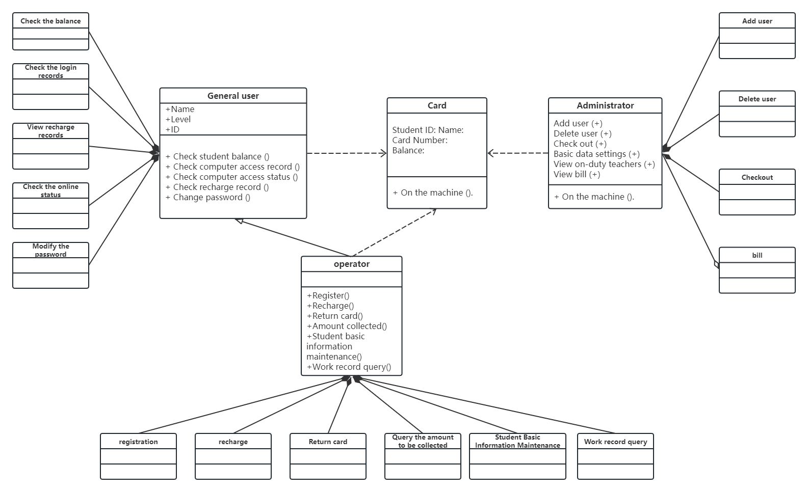
 Students surfing the Internet UML class diagram
If you can quickly read and understand the above cases, it means that you have basically understood the class diagram. Then combine some codes and corresponding class diagrams to consolidate, so that you will not be confused when you see the class diagram in the future.
ProcessOn supports the drawing of various graphics such as flow charts, mind maps, UML diagrams, architecture diagrams , etc. The method of drawing UML class diagrams with ProcessOn is very simple. As long as you master the knowledge points of class diagram drawing and understand the class diagram cases shared by the editor, I believe everyone can quickly learn to draw class diagrams.
Step 1: Register and log in to ProcessOn, create a new UML diagram
Step 2: Select the class icon in the left toolbar, drag it to the right editing area, and write the class name, properties, and methods.
Step 3: Mark the arrows and lines according to the relationship between the classes.
Note: The lines between each ProcessOn icon are solid arrows by default. You can adjust the line style, line type, line color, arrow direction and arrow style in the upper toolbar as needed. If you want to make your diagram more beautiful, you can fill the text, icons, lines, etc. with different colors and make the same icons as similar in size as possible.
The above is the relevant content about UML class diagram . All the above UML class diagram cases are drawn using ProcessOn .