Process Type
Graphical expression
Mind Type
Structured expression
Note Type
Efficient expression


Software architecture diagrams use graphical methods to clearly display the overall structure of a software system, the relationships between elements, limitations, and boundaries . They have become a core tool for enterprises to plan, develop, and manage complex software systems. This article will give you an in-depth understanding of the concepts, drawing ideas, production tutorials, and examples of software architecture diagrams , to help you better understand and apply this important tool.
A software architecture diagram is a visual representation that shows the physical implementation of the components of a software system and their interrelationships. It graphically shows the overall structure of the software system, the relationships between the elements, limitations, and boundaries. Whether it is the launch of a new project or the maintenance of an existing system, a software architecture diagram can provide a clear blueprint to help team members better understand and communicate the design and implementation of the system.
with the system architecture diagram , the software architecture diagram focuses more on the design at the software level, while the system architecture diagram covers the hardware and software components of the entire system and how they are connected. In short, the software architecture diagram is a more detailed description of the software part of the system architecture diagram.
The basic structure of a software architecture diagram usually includes the following core parts:
Definition: A component is a basic building block in software architecture, representing an independent functional unit or module in a system.
Example: In an e-commerce system, components may include user interface, order processing module, payment gateway, inventory management system, etc.
Function: To clarify the various functional parts in the system to facilitate division of labor, development and maintenance.
Definition: Relationships between components describe how they interact and collaborate with each other.
type:
Dependency: One component requires a service or functionality provided by another component.
Call relationship: One component directly calls the method or function of another component.
Data flow relationship: the path along which data flows between components.
Example: In an e-commerce system, a user interface component may depend on an order processing component to obtain order information.
Purpose: Understand how components interact with each other to ensure the correctness and efficiency of the system.
Definition: An interface is a contract for communication between components, defining the services or functions provided by the components and how to use these services.
Example: A payment gateway component might provide an interface that allows other components to call payment functions.
Function: Ensure loose coupling between components and improve the maintainability and scalability of the system.
Definition: A hierarchy is the organization of components in a software architecture, usually in layers based on functionality or responsibility.
Example: A typical web application may include a presentation layer, a business logic layer, a data access layer, and a data storage layer.
Function: Through layering, the different responsibilities of the system can be clearly divided to facilitate management and maintenance.
Definition: The deployment view describes how software components are deployed in the physical environment (e.g., servers, network devices).
Example: In a distributed system, it may include web servers, application servers, database servers, etc.
Purpose: Helps understand the physical layout of the system, facilitating performance optimization and troubleshooting.
Definition: Data flow describes the flow path of data in the system, and data storage describes how data is persisted.
Example: In an e-commerce system, user information, order information, product information, etc. need to be stored and managed.
Function: Ensure the correctness and consistency of data and support the business logic of the system.
Software Architecture Diagram Template
Before drawing a software architecture diagram, it is very important to sort out clear architectural ideas. Sorting out software architecture ideas usually includes the following steps:
Understand business needs: Have an in-depth understanding of the business areas served by the software, including business processes, business rules, business goals, etc.
Global consideration: From the perspective of the entire system, consider the relationship between each module, the interaction method, and the scalability, maintainability, performance, etc. of the system.
Anticipate future changes: Be forward-looking and foresee possible business changes and technological development trends in the future, leaving room for system expansion and upgrades.
Functional decomposition: Decompose the software system according to its functions and divide it into multiple independent modules. Each module is responsible for a specific function and has clear responsibilities and boundaries.
High cohesion and low coupling: Ensure that the functions within the module are closely related and minimize the dependencies between modules.
Focus on performance and security: Consider aspects such as system response time, throughput, resource utilization, data security, and system security.
There are many tools available for drawing software architecture diagrams, including online software, desktop software, and hand-drawing. Common tools include Visio, Lucidchart, ProcessOn, etc. Users can choose the appropriate software architecture diagram maker according to their needs.
For beginners, it is recommended to use ProcessOn , which is a professional and free online drawing tool that supports online drawing of architecture diagrams, flow charts, mind maps, etc. It provides a rich template and symbol library to help quickly create professional software architecture diagrams.
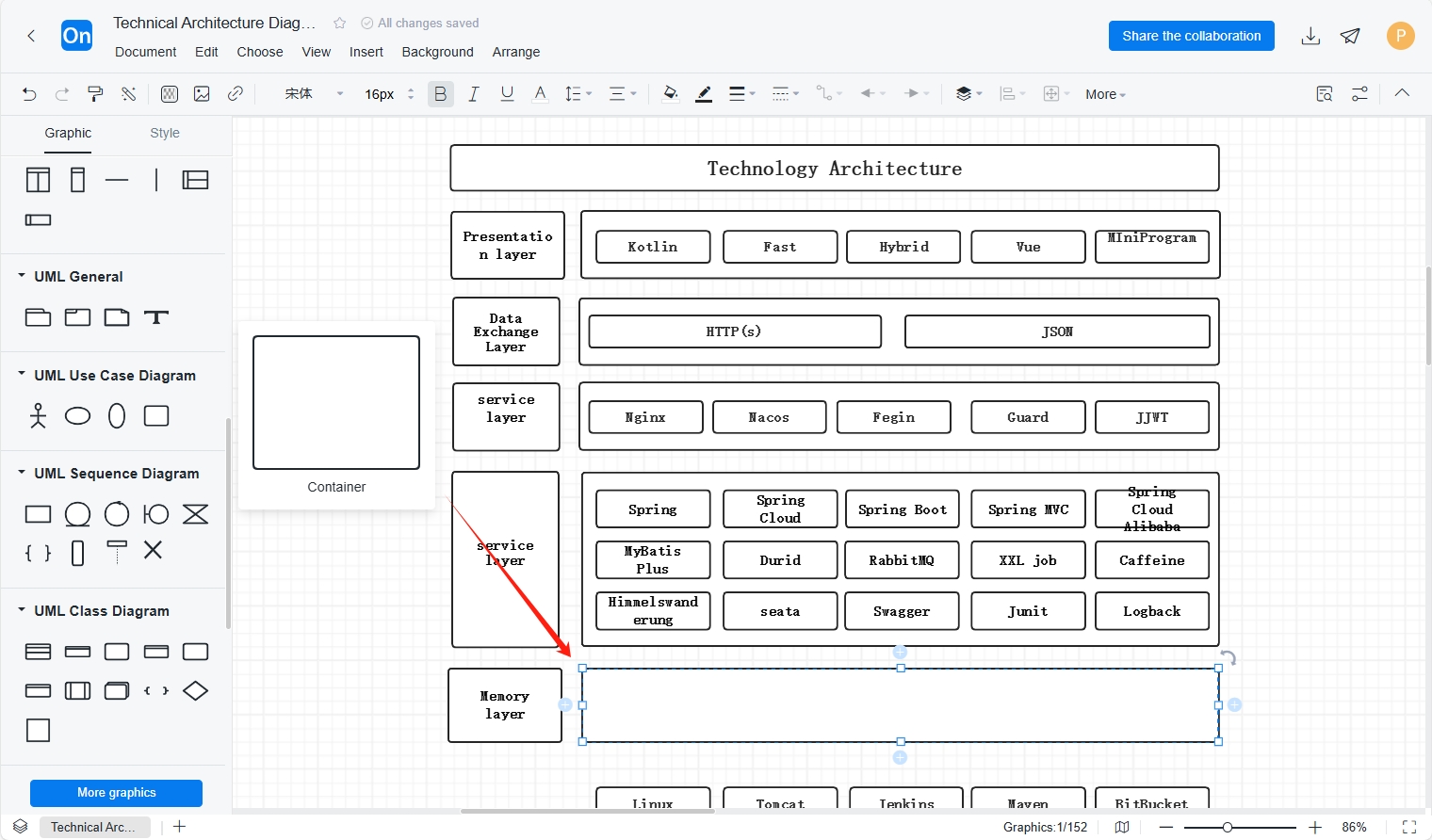
1. First, go to the ProcessOn personal profile page and click New - Flowchart in the upper left corner.
2. If the software architecture diagram you draw has a system hierarchy, you can drag the container element in the UML use case diagram to the canvas to divide the modules , such as the system layer, data layer, etc., and then drag each module component into the container. When you move the container, the elements in the container will also move with it.
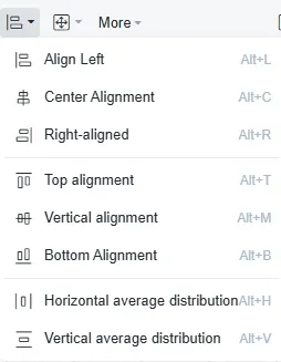
3. Next, layout the positions of the components. You can use the distribution alignment function to quickly adjust the positions of the components. For horizontal graphic alignment, select top alignment (Alt+T), vertical center alignment (Alt+M), or bottom alignment (Alt+B). For vertical graphic alignment, select left alignment (Alt+L), center alignment (Alt+C), or right alignment (Alt+R).
After adjusting the alignment, continue to adjust the distribution method. There are two distribution methods. For the horizontal graphic distribution structure, select Horizontal Average Distribution (Alt+H). For the vertical graphic distribution structure, select Vertical Average Distribution (Alt+V).
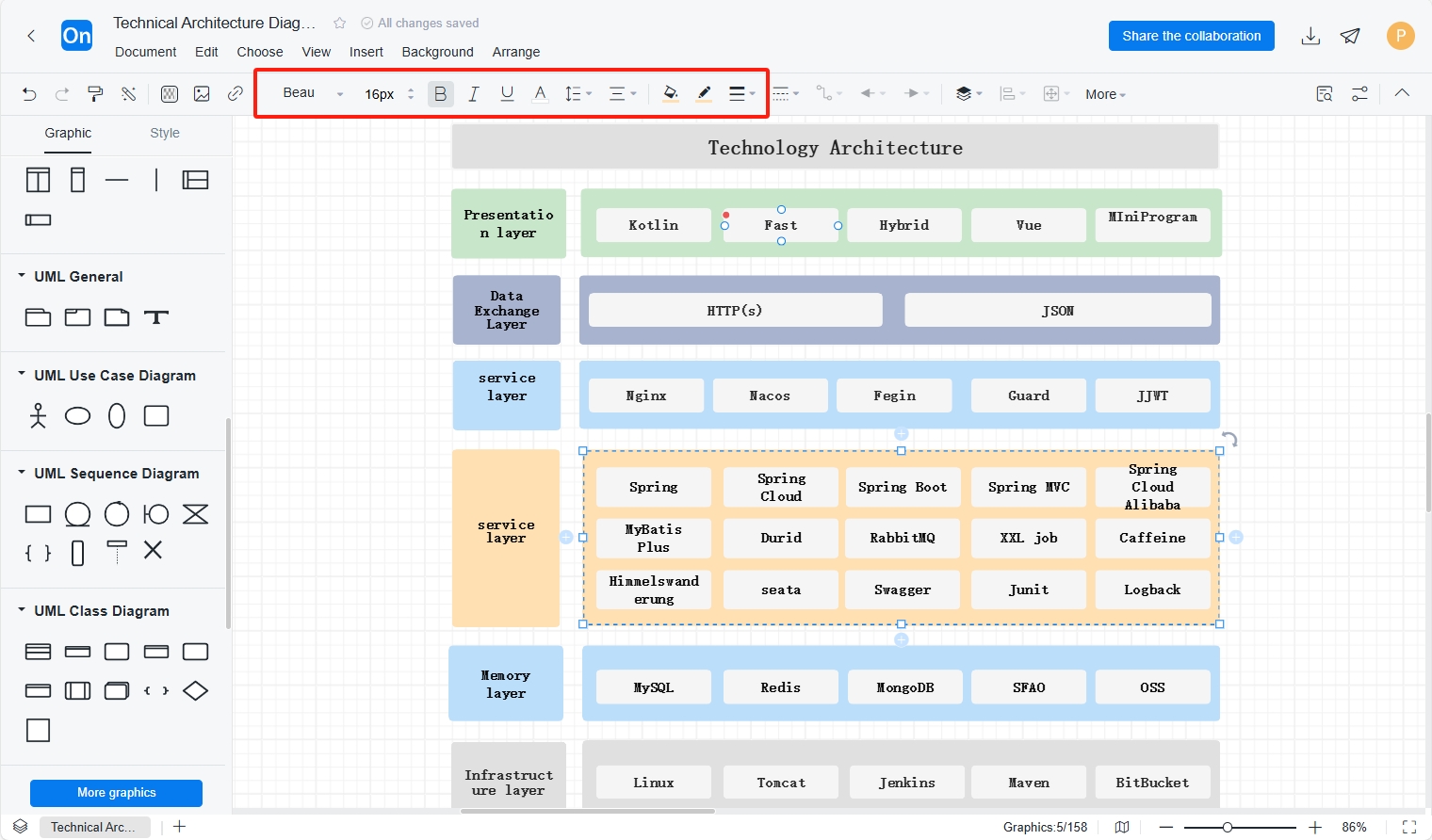
4. setting up the framework of the software architecture diagram, the top toolbar can set the color, border, font and other attributes of the graphics or lines , unify the colors of each module , and better display the overall structure and the relationship between modules .
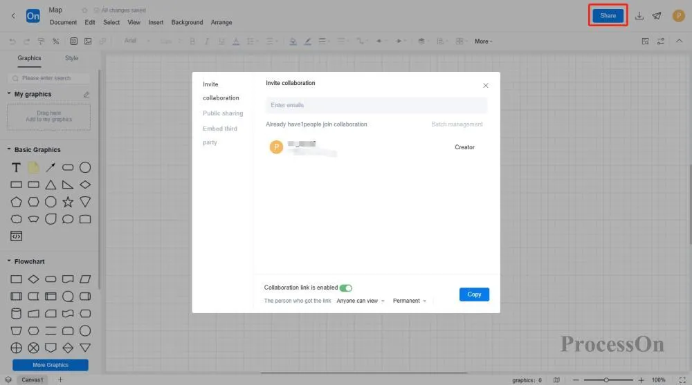
5. You can use the sharing and collaboration function provided by ProcessOn to share the software architecture diagram with team members or stakeholders for viewing or editing. You can also export it to images or PDF formats for use in other occasions.
The ProcessOn template community contains many free templates and examples of software architecture diagrams in the industry for reference. They also support copying and use to improve drawing efficiency. The following are some templates and examples .
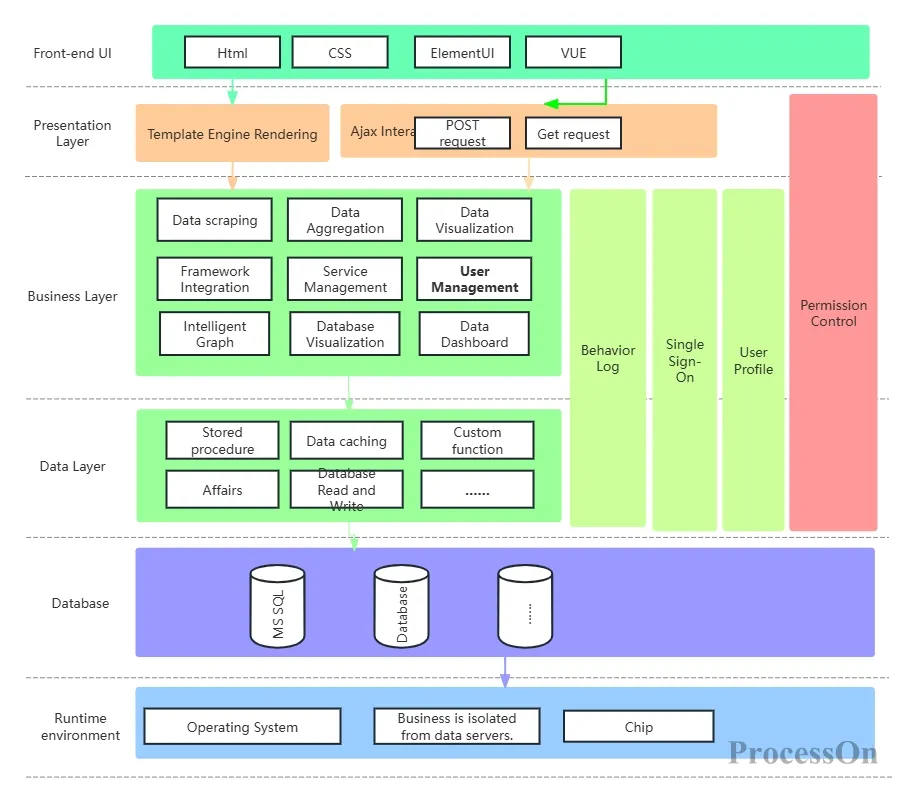
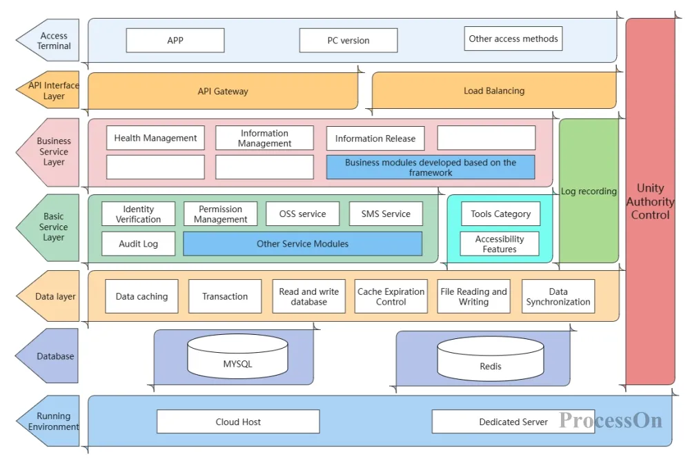
Software Architecture Diagram Template
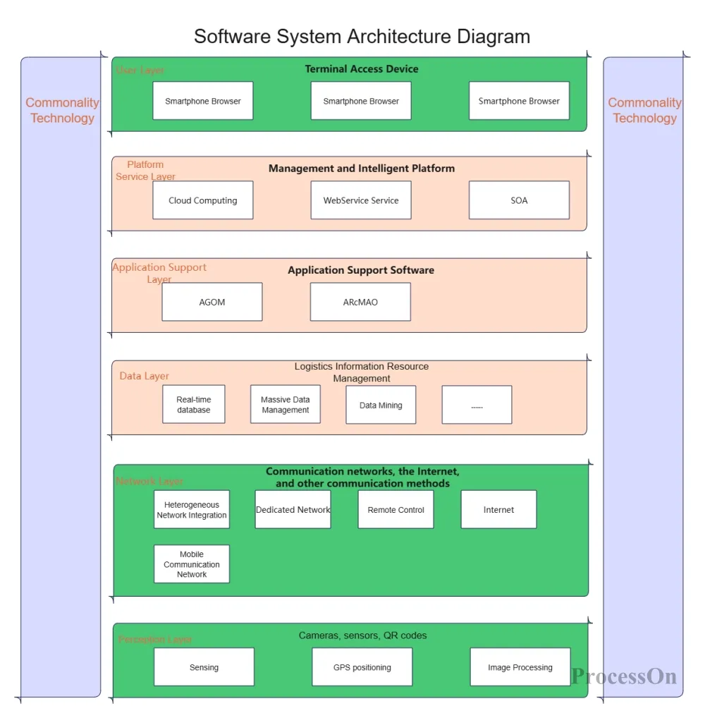
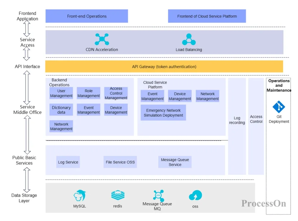
Online shopping software architecture diagram
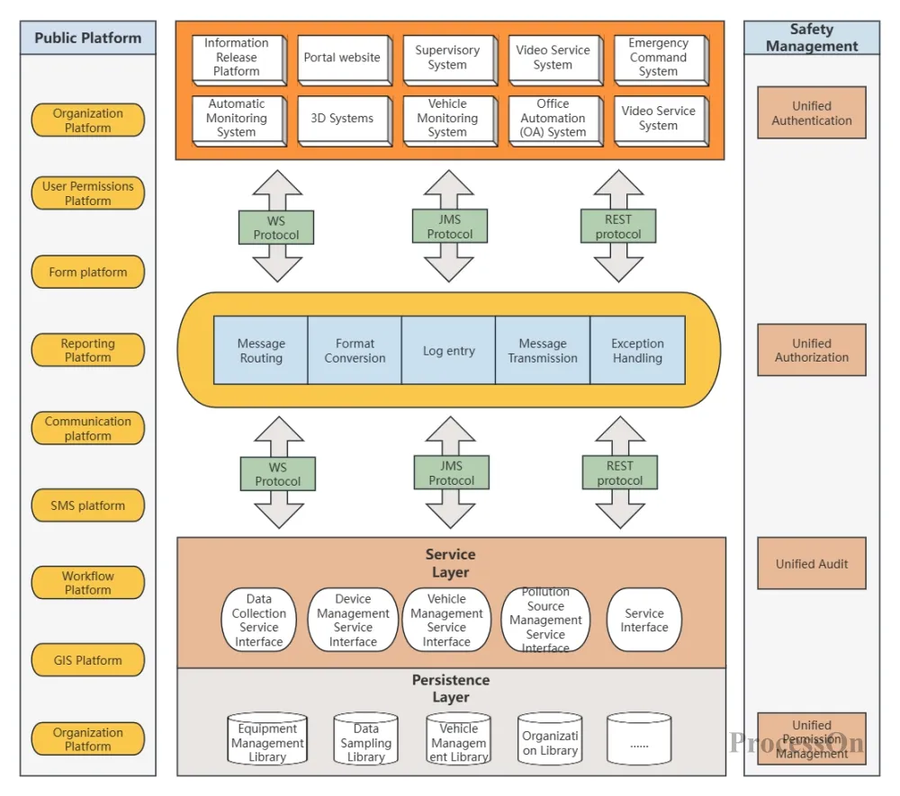
Public platform software architecture diagram
Software architecture diagrams are an important tool for understanding and communicating the design and implementation of software systems. By following the above ideas, drawing tutorials, and referring to practical examples, you can easily create professional and easy-to-understand software architecture diagrams.