In the complex and ever-changing software and system design, it is crucial to understand and predict the dynamic behavior of the system. As a core component of UML (Unified Modeling Language), the state machine diagram can help us clearly depict the various states that an object goes through in its life cycle and the transition relationship between these states. This article will deeply analyze the concept, composition , drawing tutorials, templates and examples of the state machine diagram . I believe that after reading this article, you will be able to master the state machine diagram .
State Machine Diagram, also known as State Diagram , is a state-based modeling method that graphically displays the various states that an object goes through during its life cycle and the transition conditions between states.
The function of the state machine diagram is to clearly describe the transition sequence between states, as well as the events that must be triggered during the transition, the monitoring conditions and actions, and other factors that affect the transition.

E-commerce order state machine diagram
The state machine diagram consists of state nodes, transition arrows, and possibly additional trigger events, guard conditions, actions, etc. State nodes are usually represented as rounded rectangles or ellipses, while transition arrows indicate the path from one state to another.
Definition: A state is a condition of an object during its life cycle when it meets certain conditions, performs certain activities, or waits for certain events.
type:
Initial state: represents the state of the class when it is created, represented by a black solid circle. A state machine diagram can only have one initial state.
Final state: represents the state of the class at the end of the execution flow, represented by a black solid circle with a ring. A state machine diagram can have multiple final states.
History state: used to record the state that the object has reached, so as to quickly restore to that state under certain conditions.
Simple state: A state that does not contain any substates and is the basic form of a state.
Composite state: A state that has substates nested inside it, which can be sequential or concurrent substates.

Elements of the general state:
Name: It is composed of a string used to identify different states and is usually placed on top of the state icon . It can also be omitted.
Action: includes entry action (action executed when the object enters a certain state) and exit action (action executed when the object leaves a certain state). Action can be atomic action or action sequence .
Activities: Internal activities that contain expressions, represent non-atomic execution in a state machine, and generally consist of a sequence of actions.
Internal transition: An internal transition does not cause a state change. The triggering of this transition does not cause the entry/exit actions of the state to be executed.
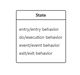
Definition: A transition is a process by which an object moves from one state to another.
Components:
Source State: A source state is a state that is affected by a transition. When an object is in a source state, a transition is activated when it receives a trigger event or satisfies a guard condition.
Events: An event is an external or internal stimulus that causes a change in state.
Guards: are the conditions for the original state to transfer to the target state. The guard conditions are judged when the original state ends. Only when the guard conditions are met can the state be transferred to the specified target state.
Action: Indicates the effect called on the object when a state change occurs, separated from the event by "/".
Target State: The state of the object after the transfer is completed.

State machine diagrams are an important tool in system design and development. They can help us:
Explicit state: Clearly define the state of an object at different points in time.
Understand transitions: Uncover the conditions and triggering events for transitions between states.
Optimize logic: With the state machine diagram , we can more easily find potential logic errors, such as omissions or conflicts in state transitions.
Improve readability: Graphical representation makes the state machine diagram more intuitive and easier to understand than plain text description.
State machine diagrams are widely used in various fields such as:
Embedded systems: Describe the state transitions of a device in different operating modes.
E-commerce: Show the various states of an order from creation to completion.
Game development: define the character's state and actions at different game stages.
Industrial automation: Control the state transition of machines in different working modes.
Taking the order processing system as an example, the state machine diagram can clearly show the entire process of an order from "creation" to "successful payment" to "shipping" and "completion".
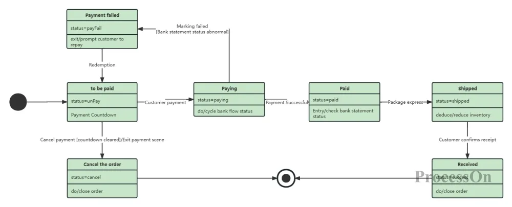
Order processing state machine diagram
Drawing a state machine diagram usually follows these steps:
Determine the object: Identify the object or system to be modeled.
List States: Identify and list all the states that an object may go through during its life cycle.
Define transitions: Determine the conditions and triggering events for transitions between states.
Draw graphics: Use a UML maker (such as Visio, ProcessOn , etc.) or draw by hand to draw state nodes and transition arrows.
Add details: Add details such as trigger events, guard conditions, and actions to state nodes and transition arrows.
drawing state diagrams , and it is very important to choose a tool that suits your needs. Common tools include Visio, draw io, ProcessOn, etc. Users can choose the appropriate state diagram maker according to their needs. For beginners, it is recommended to use ProcessOn , which provides rich templates and an easy-to-use interface. Here we mainly explain how to use ProcessOn to make a state machine diagram.
1. Log in to ProcessOn , go to the Personal Files page, and select Create New UML Diagram.
2. Find the [UML] category in the graphics library on the left, drag the state diagram graphic to the canvas, double-click the graphic to add text, and click the "+" around the graphic to add connections to other graphics.
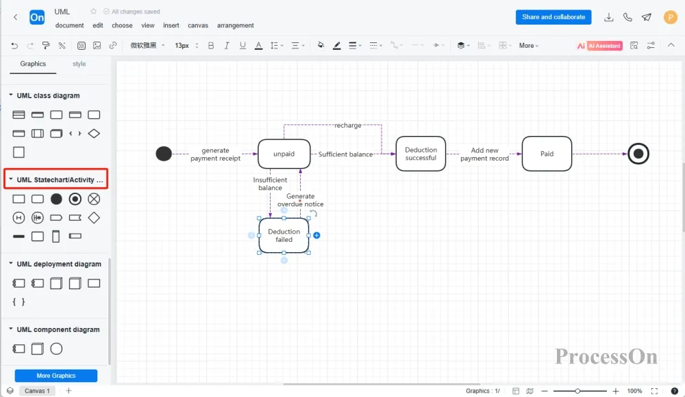
The following are some state machine diagram templates shared in the ProcessOn template community .
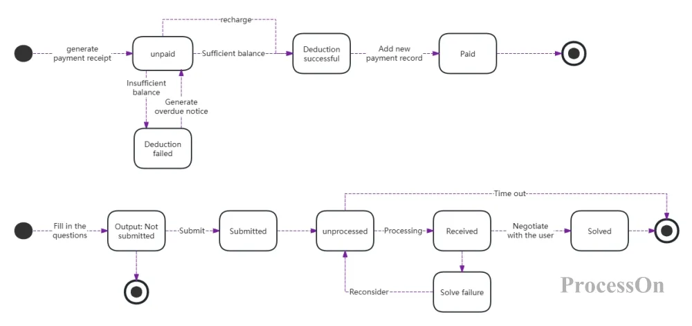
Recharge and feedback status diagram

Airline Ticket Reservation System State Machine Diagram
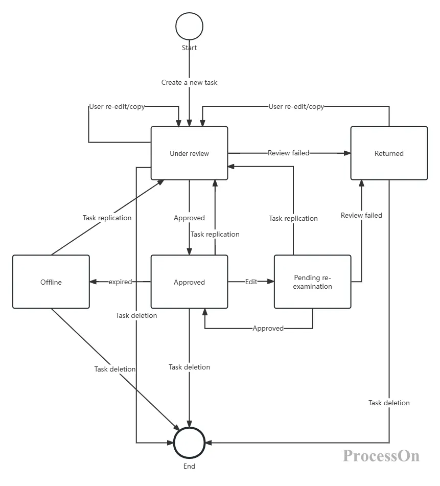
Task Center State Machine Diagram
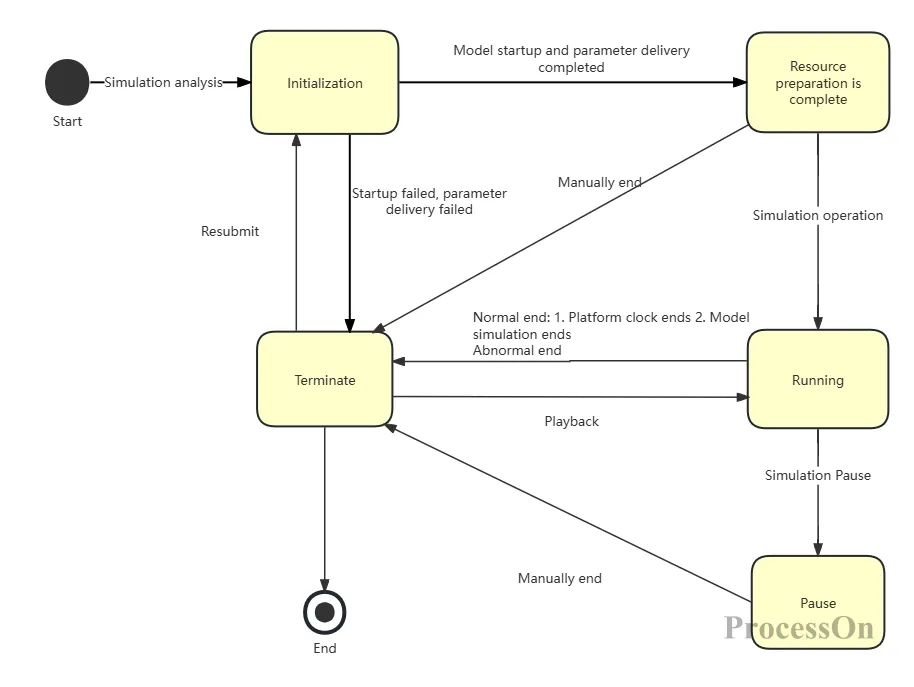
Simulation state machine diagram
important role in system design and development . It clearly describes the transition sequence between states and the order of event execution. It helps programmers avoid the misorder of events when developing programs. I believe that after understanding the drawing method and cases , you can better understand and apply this tool.