AWS (Amazon Web Services) is the world's leading cloud computing provider. The AWS architecture diagram is a visual tool that depicts the connections and interactions between AWS resources, services, and components. These resources and services may include computing instances (such as EC2), storage solutions (such as S3), databases (such as RDS), network configurations (such as VPC), etc. Through the architecture diagram, users can clearly see how their AWS environment is built and how the various components work together.
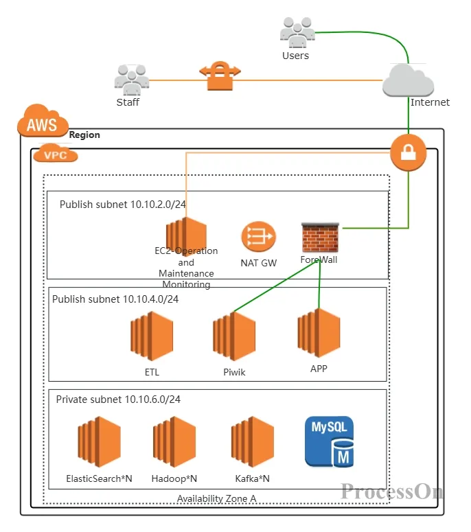
Data Platform-AWS Architecture Diagram
Project planning: In the early stages of a project, use architecture diagrams to plan the deployment and configuration of AWS resources.
Troubleshooting: When a fault occurs, use the architecture diagram to quickly locate the problem and take appropriate solutions.
Training and knowledge transfer: Use architectural diagrams to show team members or customers the layout and working principles of the AWS environment.
Compliance and Auditing: During compliance reviews and audits, use architecture diagrams to demonstrate that the configuration of your AWS environment complies with relevant standards and requirements.
AWS architecture diagrams use a series of standardized symbols to represent different services and components. These symbols generally follow the conventions in AWS official documentation and are connected by arrows to indicate data flow and connection direction.
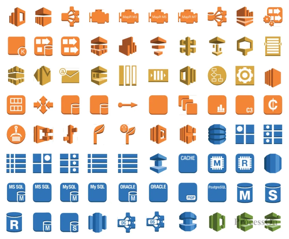
Some AWS architecture diagram symbols
A complete AWS architecture diagram usually contains the following key components:
1. Core service components
VPC (Virtual Private Cloud): Virtual Private Cloud is the core of AWS network services, allowing users to configure logically isolated parts of the AWS cloud. Users can launch AWS resources in their own defined virtual networks in this isolated environment.
AZ (Availability Zone): Availability Zone refers to one or more discrete data centers in an AWS region with redundant power, network, and connectivity. Each AZ is designed to be isolated from failures in other AZs and to provide cheap, low-latency network connectivity to other AZs in the same AWS region.
2. Network connection components
IGW (Internet Gateway): Internet Gateway is the gateway between VPC and the Internet, allowing resources within the VPC to access the Internet and vice versa.
VGW (Virtual Gateway): A virtual gateway, a VPN concentrator used for site-to-site VPN connections between VPCs and enterprise data centers.
VPC Peering: A VPC peering connection allows you to connect two VPCs and route traffic between them using private IPv4 or IPv6 addresses.
Transit Gateway: A transit gateway acts as a network transit hub, connecting multiple VPCs, VPNs, and AWS accounts together, reducing the complexity of managing multiple connections.
VPC Endpoint: VPC endpoints allow VPCs to privately connect to AWS services powered by PrivateLink and VPC endpoint services without the need for an internet gateway, VPN, or NAT device.
3. Security and access control components
VPN (Virtual Private Network): A virtual private network used to establish a secure connection on a public network.
AWS PrivateLink: Provides private connectivity between your VPC and AWS or services hosted on-premises, ideal for secure access to SaaS applications.
Security Group: The security group associated with an ENI (Elastic Network Interface) defines the traffic rules allowed to enter and leave the network interface, providing network-level security control.
There are many tools for drawing AWS architecture diagrams, and it is very important to choose a tool that suits your needs. Common tools include Visio, draw io, ProcessOn, etc. Users can choose a suitable state diagram maker according to their needs. For beginners, it is recommended to use ProcessOn , which is a professional flowchart tool that supports online drawing of architecture diagrams. It provides a wealth of AWS symbols and templates.
1. Open ProcessOn official website, enter the personal file page, click New to create a flowchart
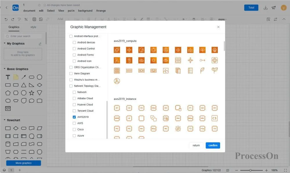
2. Click More Graphics in the graphic gallery on the left, find [AWS] and [AWS2019] in the network topology diagram, and click OK.
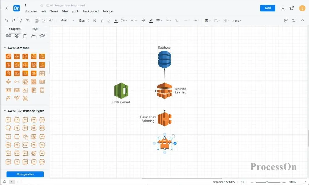
3. the AWS architecture diagram symbol from the graphic library on the left side of the flowchart maker to the canvas, double-click the graphic to add text, and click "+" on the graphic to create connections between different AWS symbols.
4. After completing the architecture diagram, you can share the file with colleagues or customers for review and editing.
When drawing an AWS architecture diagram, paying attention to the following details will help improve the accuracy and readability of the diagram:
Clear Labeling: Make sure every component and connection is clearly labeled and described.
Hierarchy: Use a hierarchy to present different levels of components and services to highlight key points and simplify diagrams.
Color Coding: Use color coding to distinguish different types of components or services to make the diagram more intuitive.
Comments and Notes: Add necessary comments and notes to explain complex configurations or decisions.
The ProcessOn community contains a wealth of AWS architecture diagram templates and examples for reference, and supports cloning to improve drawing efficiency. The following are some examples.
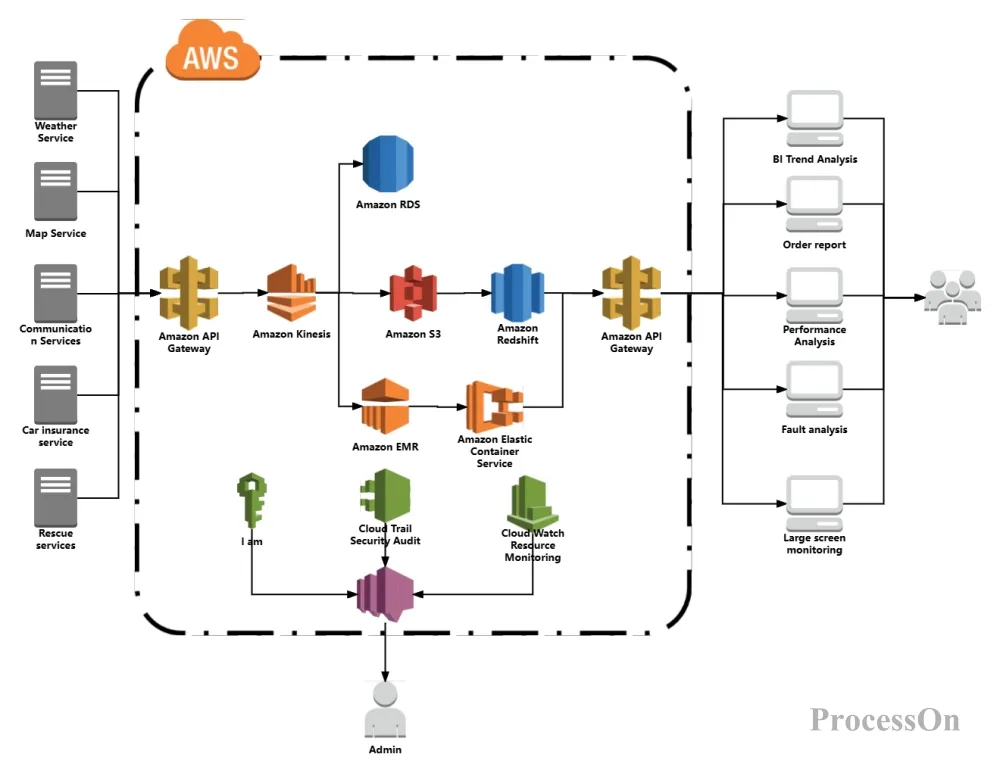
AWS Architecture Diagram Example
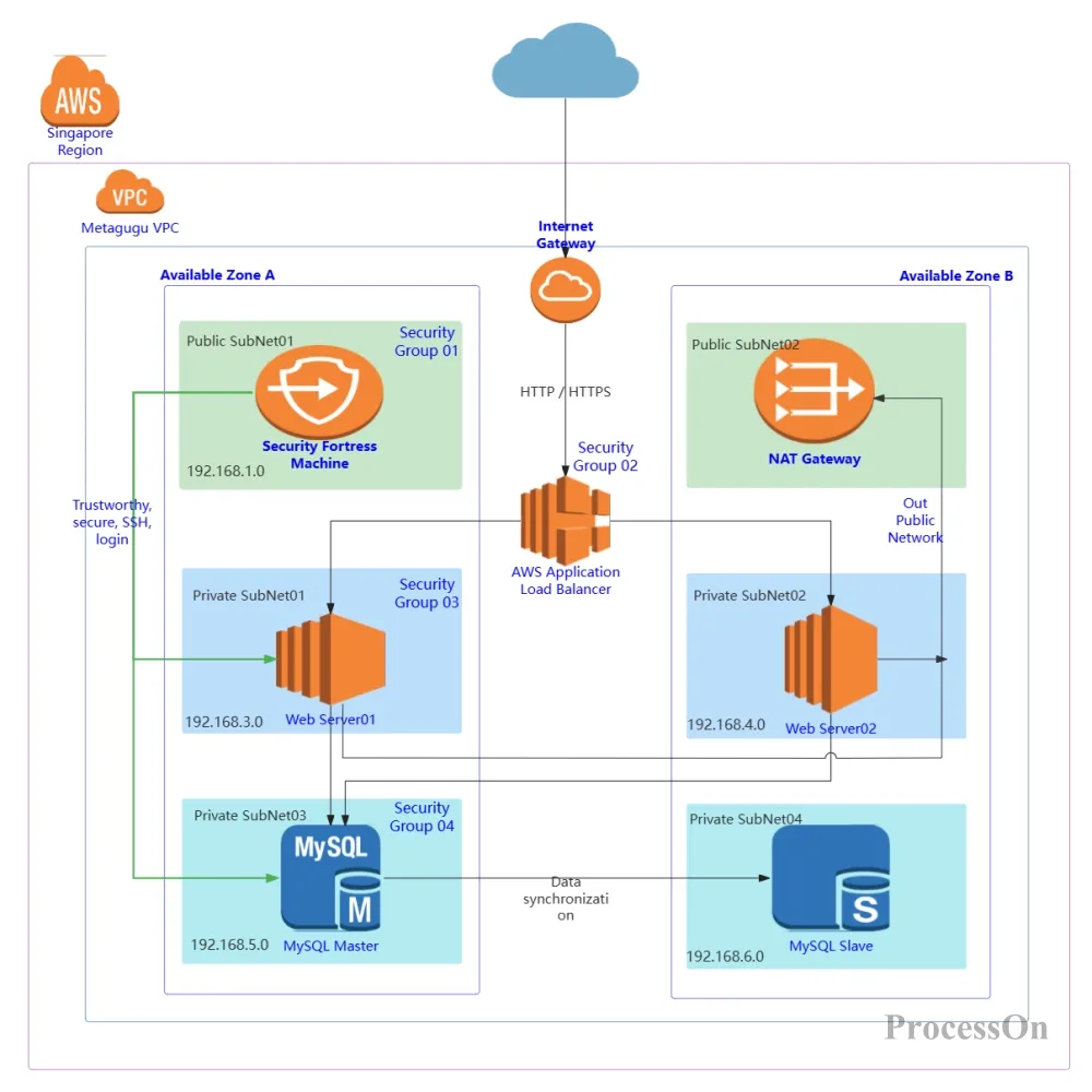
Minimum business architecture on AWS cloud
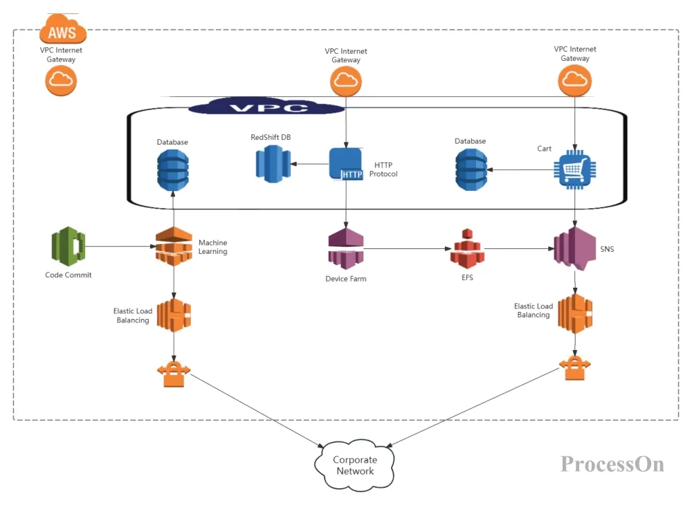
AWS Architecture Diagram Template
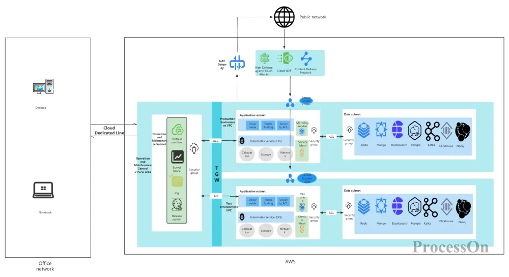
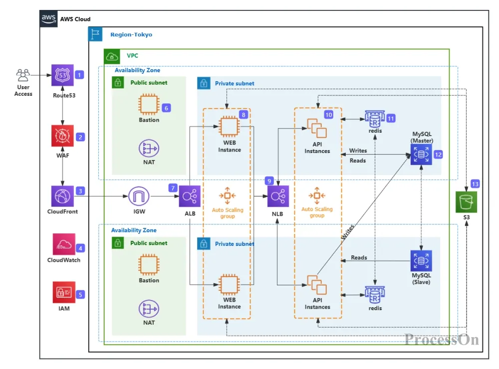
AWS architecture diagram is an important tool for understanding and optimizing AWS environment. By deeply understanding its definition, composition , symbols , etc., you can better plan and manage AWS resources, thereby improving the efficiency and security of your business.